AUSTIN SEVEN ENGINE REBUILD
Article kindly
reproduced from the Herefordshire A7 Club.
Part 8 - Attaching the block
& cylinder head
Part 1 – The crankcase,
camshaft, oil pump, rear main housing.
Part 2 - The
cylinder block, connecting rods and main bearings
Part 3 -
Crankshaft & con rods
Part 4 -
Main Bearings
Part 5 -
Carburettors, manifolds, clutch and fan spindle
Part 6 - Flywheel
Part 7 - Reassembly
Attaching the block:
If the crankcase has been prepared as discussed in Part
1, we can now attach the block - but first, I use a thin ‘Dremel’ type cutting
disc to make four cuts in each oil baffle and bend open the ‘wings’ just enough
to let the big-end pass through. These opened baffles are then placed in the top
of the crankcase with the small nibs sitting neatly in the crankcase recesses to
ensure they are correctly positioned. The top of the crankcase and the bottom of
the block are de-greased and a thin layer of sealant (again, I use ‘Blue
Hylomar’) applied to the outer contact areas of both items. After a few minutes
wait, the block is placed in-position and secured by firmly tightening the eight
5/16” nuts on new locking washers. I then attach my extra ‘holding-down’
brackets at the front and rear of the block as described in an earlier part.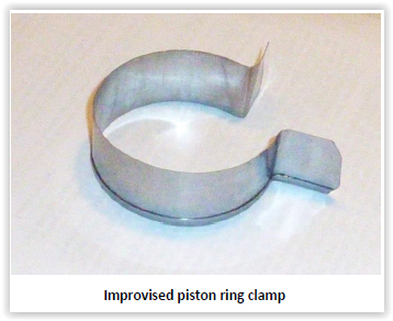
Before fitting the pistons in the block, the rings should be rotated in their
grooves to position the gaps approximately 180 deg to the gaps in adjacent
rings. This helps to maximise compression by presenting the most difficult route
for any gasses escaping past the pistons.
‘Real’ engine builders use proprietary piston ring clamps but mine was cut from
an old tin can many years ago (see photo) and with everything liberally
lubricated and a firm grip - it works a treat. It is obviously important not
force the piston & ring assemblies into the bores because you might break a ring
but if the rings are correctly gapped and firmly clamped, they will happily
slide into position.
As each piston/rod assembly is inserted into the block, I attach its (well
lubricated) big-end to the crankshaft using new bolts and new deep self-locking
nuts (it’s difficult to fit a socket on the shallow ones), having carefully
noted the position of the rod orientation markings. The big-end nuts should next
be torqued-up to 18 lb.ft, followed by a quick check that everything rotates
smoothly. Finally, the ‘wings’ of the oil baffles can be closed whilst ensuring
they remain clear of the rods.
It is very important that the cams are properly lubricated before first starting
a new engine so I coat mine at this stage with EP 140 (back axle) oil.
Sump etc
I like to use a semi-deep aluminium sump because it
gives usefu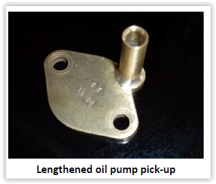 l
additional capacity and also stiffens the engine. However, this requires a
simple modification to the oil pump bottom plate. The one shown here has a
lengthened pick-up pipe ‘silver soldered’ in position. Incidentally, very deep
sumps are available, but they make life rather difficult if you try to install
or remove the engine with the sump attached.
l
additional capacity and also stiffens the engine. However, this requires a
simple modification to the oil pump bottom plate. The one shown here has a
lengthened pick-up pipe ‘silver soldered’ in position. Incidentally, very deep
sumps are available, but they make life rather difficult if you try to install
or remove the engine with the sump attached.
The sump gauze and sump can now be fitted and this will enable the engine to sit
more comfortably on the bench.
Flywheel & clutch
Run-out has previously been checked and adjusted, so
assemble the flywheel with its woodruff key in position on tapers that are dry
and clean. Check the flywheel nut has a good thread and tidy flats - but replace
with new if in doubt – then, with a new locking tab in position apply a thin
film of medium strength thread-lock and tighten the nut very, very firmly.
Preventing the crankshaft from turning is probably most safely achieved by
placing a good sized softwood block inside a strong area of the crankcase. I
have read that a drift poking out of the flywheel rim and resting on the top
edge of the crankcase can be used to lock the crankshaft. However, I have seen
broken crankcases that look as if they have suffered from this method and
several others sporting cracks hereabouts, all of which seems to suggest that
this is probably not a great approach!
Clutch assembly and the insertion of the ‘mousetrap’ springs is very
straightforward if you have three nice long ¼” BSF bolts with nuts and washers.
A clutch plate alignment bar is also essential, I made mine in about ten minutes
from a mild steel bar many years ago and the dimensions can be found on page
A5-11 of Woodrow.
Valves & springs etc
Assembling A7 valve gear is well described in numerous books so I will
not repeat it here. However, there are one or two points perhaps worth
mentioning:
• Always use valves that are retained by cotters rather than pins
• Double valve springs (if used) should be accompanied by appropriate cotter
retainers
• ‘Flick’ the bottoms of assembled valves with a screwdriver to make sure the
cotters are fully seated before checking clearances
• Set tappet clearances at 4 thou’ for both inlet and exhaust when using a
standard A7 camshaft and this makes for a nice quiet engine. Interestingly,
Woodrow reckons 6 thou’ inlet and 7 thou’ exhaust. For sporty high lift
camshafts, use 6 thou’ inlet and 8 thou’ exhaust although this makes the engine
quite noisy at tick-over
• When adjusting tappet clearances, use the ‘sum of nine’ method. For example,
adjust one when eight is open, two when seven is open etc etc. Or you can simply
adjust the inlet and exhaust tappets when the piston of that cylinder is at TDC
on the compression stroke
Cylinder head
Carefully tighten cylinder head nuts (over flat washers) incrementally in the
recommended sequence to 18 lb.ft, this is perfectly adequate. I have seen 22
lb.ft or more suggested and I believe this figure is too high and maybe the
cause of cracks in the block around the centre stud (mentioned in Part 3 of
these notes). Blocks with re-lined bores are particularly vulnerable.
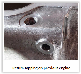
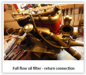
External oil filter
I described a full-flow external cannister type oil filter in Part 1
and the photo on the left here shows how it is connected to the engine. My spare
engine also has an external oil filter, but its return connection was drilled
and tapped (with some difficulty) into the top of the main gallery just behind
the dynamo as shown in the photo on the right. The new approach is less tidy but
definitely much easier.
Finally, it is important that dynamo bearings are in good condition and there
should be no discernible end-float. We can now set the engine timing. I do this
by removing the spark plug from No 1 cylinder and rotate the engine (using the
starting handle or by pushing the car forward in top gear) with my thumb over
the plug hole. It is then easy to detect the compression stroke and set the
distributor so that the points are about to open with the rotor arm pointing in
the direction of the No 1 HT plug lead. Thus set - the engine will invariably
fire-up and run, then when warm, I rotate the distributor anti-clockwise (viewed
from above) to advance the engine until it sounds very slightly rough, then
back-off a little. Someone once said: “Start with it very slightly advanced then
retard it bit at a time until your lap times increase”.
Well, that’s about it and I hope the reader has found these ramblings to be of
some interest
.
Spanner Article kindly reproduced from the Herefordshire A7 Club.