AUSTIN SEVEN ENGINE REBUILD
Article kindly
reproduced from the Herefordshire A7 Club.
Part 5 -
Carburettors, manifolds, clutch and fan spindle
Part 1 – The crankcase,
camshaft, oil pump, rear main housing.
Part 2 - The
cylinder block and connecting rods
Part 3 -
Crankshaft & con rods
Part 4 - Main Bearings
Part 6 - Flywheel
Part 7 -
Reassembly
Part 8 -
Attaching the block and cylinder head
Carburettors and
manifolds
I have personal experience of a variety of different
carburettor & manifold combinations on both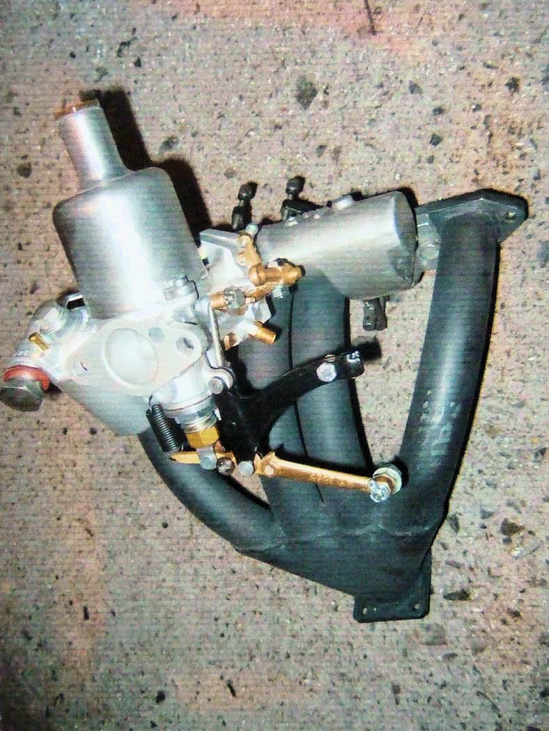 standard and mildly tuned road-going
Austin Seven engines and my findings are summarised in the following notes.
However, I do not include details of the selection, adjustment and maintenance
of specific carburettors, because there is already a wealth of information
available and indeed whole books written on the subject.
standard and mildly tuned road-going
Austin Seven engines and my findings are summarised in the following notes.
However, I do not include details of the selection, adjustment and maintenance
of specific carburettors, because there is already a wealth of information
available and indeed whole books written on the subject.
In my experience it pays to ensure that manifold
passageways are generally smooth with no sharp steps or corners. It can
sometimes be useful to remember our basic fluid mechanics theory here, that
tells us sudden enlargements are a greater source of friction loss than sudden
contractions of similar proportions. An interesting fact and perhaps somewhat
counter-intuitive.
It is often necessary to remove material to achieve
reasonably smooth passageways and this can be achieved with small grind stones
in a hand-held drill or ‘Dremel’ style flexible drive. It is also important to
remember that gaskets might need trimming to ensure they don’t interfere with
the smooth flow of gas.
I believe the inlet tract is more important than the
exhaust and I am not convinced that a polished finish is necessary in a touring
engine. The photo shows a reasonably smooth gas flow path in a current A7 engine
that performs remarkably well.
Many Chummy owners claim surprisingly good
performance with the Updraft 22FZ Zenith carburettor in conjunction with
standard early Austin cast-iron and alloy manifolds. However, I believe this
might have more to do with the light weight of these cars, than efficient
breathing of the engine, because the gas path is unarguably torturous.
My experience is that a side-draft 26VA Zenith
mounted on the Ruby type standard Austin cast iron manifold does offer a slight
increase in power. This is especially noticeable if the narrow throat of the
inlet is opened up from the standard 0.75” Dia, to say 0.95” Dia and the
internal corners nicely rounded.
However, I have a personal preference for SU
Carburettors. They seem to suit Austin Sevens rather well, are often easier to
set-up and being based on a variable jet principle, they enable any slight
blockage to be easily overcome by tugging briefly on the choke. Back in the
Sixties, many A7s sported twin SU carburettors but unless you plan to de-siamese
your inlet ports, it now seems widely accepted that a single instrument will be
more effective and of course a good deal easier to set-up. Whilst on the subject
of jet blockage, I always employ a fuel filter. My preferred type has a fine
brass mesh above a small glass bowl in which I often find small amounts of
debris which are easily removed. One purchase of petrol in rural France on the
2017 Eurotour caused the glass bowl to become completely full of fine grit
particles but happily, nothing reached the float chamber.
So what size and configuration of SU carburettor do I
favour? Well, I have had good results with a 1.00” Dia (measured at the
butterfly) horizontal sidedraft SU fitted to the standard Ruby style
inlet/exhaust manifold; which seemed to give a further improvement in
performance over the 26VA Zenith on the same manifold.
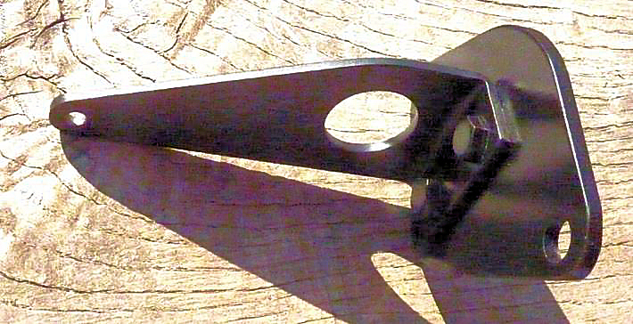
However, a more tasty option is a 30o
1.125” Type H1 SU mounted on an ALR (or similar) alloy inlet manifold with 30o
flange, in conjunction with an ‘bunch of bananas’ steel exhaust manifold such as
the one shown here made by Ian Bancroft.
This combination has worked extremely well for me for
some years but fitting it in-place is not entirely straightforward. Firstly,
there is no room for the centre manifold stud, so this must be blanked-off,
which means the other studs need to be in really good shape. I have previously
mentioned that Sir Herbert’s offerings seem a little frail at ¼” Dia. so I
always make mine 9/32” Dia.
Access to several of the manifold nuts is also
severely restricted with this particular exhaust arrangement, which makes the
length of the studs somewhat critical. Even then, there is insufficient
clearance to accommodate a conventional socket for tightening the nuts. So, I
have resorted to an old box spanner with some material ground-off its outer
surface. Clearly, for structural reasons, it is important not to overdo this
grinding or let it get too hot which would destroy its temper. Happily, old box
spanners are often made of excellent steel and my ground-down version has lasted
many years.
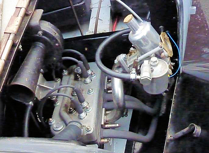
Box saloons (and I guess Rubies) have plenty of room
to accommodate a ‘bunch of bananas’ exhaust manifold but with a ‘Chummy’ it is
more of a squeeze. An easier option in this case, is a swept four branch exhaust
manifold such as that supplied by Pigsty Racing and a fine example can be seen
in the photo on the left of one of our Club cars.
Clearly, with sports exhaust manifolds you have to
make your own arrangements for connecting the exhaust pipe because standard
exhausts will not fit directly. Actually, I have found that they sometimes don’t
fit terribly well even in unmodified cars.
Another interesting option is a Nippy manifold.
Interesting, firstly because it will accommodate a standard exhaust downpipe and
secondly because it seems surprisingly efficient. This efficiency might derive
from a masterpiece of theoretical Longbridge calculation but some argue it is
more likely a happy accident of design. Never mind, it works really well.
Unfortunately, the correct Nippy downdraft Zenith
carburettor (the 30 VE1) has become an endangered species, the last one I saw
for sale about five years ago was severely damaged and still had an asking price
of well over £200. However, several other similar Zeniths make excellent
substitutes and often come-up for sale at reasonable prices. There is also
plenty of available information on suitable choke and jet sizes. 26
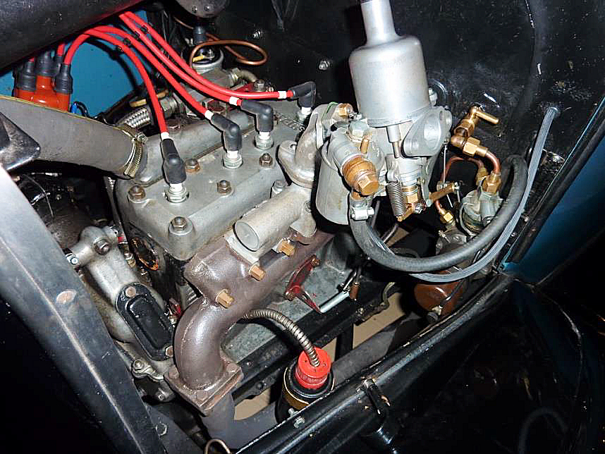
For those of us that prefer a variable jet in our
carburettors, it is fairly straightforward to fit a 30 degree aluminium adaptor
to a Nippy manifold as shown in the photo. Standard adapters are available but
the ones I have seen are designed to take a 1.25” HS2 SU, which I believe might
be slightly too big for my road engines.
However, with a little ingenuity, these adapters can
be modified to take a 1.125” H1 SU and I am currently enjoying excellent results
with this configuration. As a point of interest I am currently using a GG needle
which seems about right.
The photo also shows my oil catch tank. The valve
chest cover breather holes are blanked-off and an adapter connects (via a length
of old outer speedo cable) to an old Brasso tin that has a ring of small holes
in its lid. It works surprisingly well.
Since this photo was taken, I have added a short
home-made inlet trumpet, fitted with a coarse gauze to prevent any unwanted
large lumps of grit from entering the engine. It seemed a good idea and there is
just enough room under the bonnet - but it has had no noticeable effect on
performance. At some stage I propose to experiment with some form of air-cleaner
cum silencer but for the moment, I shall continue to enjoy the noisy roar of the
engine, especially noticeable on wide throttle openings.
Clutch
The benefits of even a slightly sporting engine will
obviously be lost if the clutch is in poor shape.
 Therefore
unless the linings are obviously fairly new, I invariably replace them when
building an engine. Austin Seven clutch linings are not wildly expensive, they
are dead easy to fit and it gives enormous peace of mind. Similarly, a set of
new clutch springs is also a good idea if yours look a bit compressed compared
to new ones which are typically 1.375” long. Incidentally, although some people
recommend them - I have never felt the need for double clutch springs, even with
fairly pokey engines. Maybe clutch slip is more frequently caused by oil
sneaking into the clutch?
Therefore
unless the linings are obviously fairly new, I invariably replace them when
building an engine. Austin Seven clutch linings are not wildly expensive, they
are dead easy to fit and it gives enormous peace of mind. Similarly, a set of
new clutch springs is also a good idea if yours look a bit compressed compared
to new ones which are typically 1.375” long. Incidentally, although some people
recommend them - I have never felt the need for double clutch springs, even with
fairly pokey engines. Maybe clutch slip is more frequently caused by oil
sneaking into the clutch?
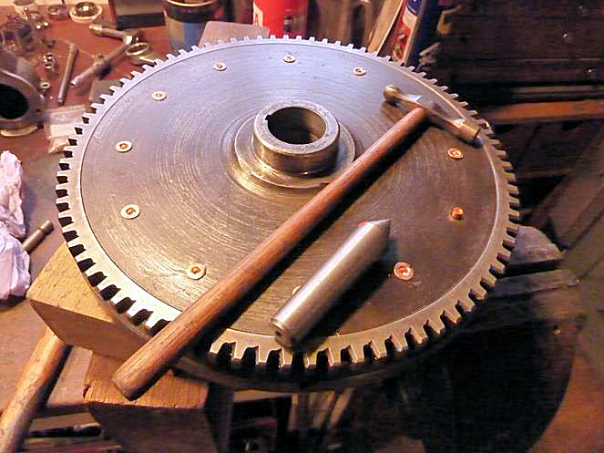
The above photos show a new clutch lining fitted to a
flywheel. I use a mild steel ‘dolly’ of rivet head diameter held in the vice to
support the lining side of the rivet and prop the flywheel in a horizontal
position. I then use a lathe ‘dead centre’ to initially spread the hollow copper
rivet before widening them a little further with the ball-pein end of a small
hammer then finally spread it just enough to hold things firmly together. A
similar approach is followed to re-line the pressure-plate.
A smooth operating clutch also requires the pillars,
clutch levers and pivot pins to be in reason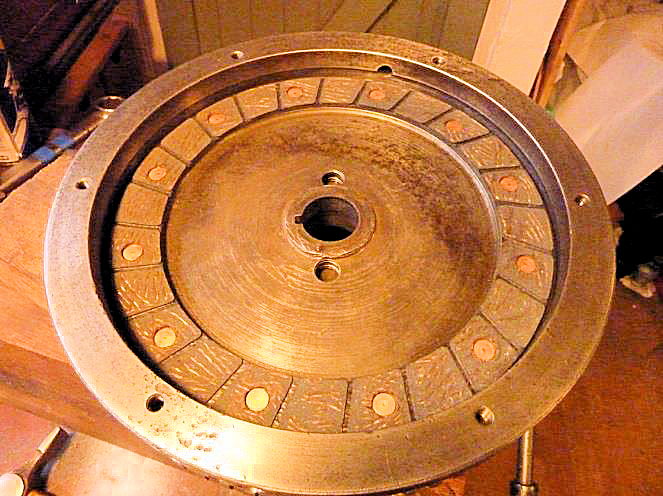 able
condition. New replacement items are available, mostly at reasonable prices
except that a set of three levers will set you back approaching £30. No wonder
it’s common to apply weld to the worn faces and then file them to shape. Play in
the lever pivots can sometimes simply be removed by replacing worn pins with
lengths of 5/16” silver steel. Some books suggest removing wear with oversize
pivot pins and reaming the pillars but this will do your reamer no favours
because the pillars are hardened steel, therefore new items might be a better
option. Woodrow tells us the pivot pins should be a press fit in the levers but
I have found that this is not always the case.
able
condition. New replacement items are available, mostly at reasonable prices
except that a set of three levers will set you back approaching £30. No wonder
it’s common to apply weld to the worn faces and then file them to shape. Play in
the lever pivots can sometimes simply be removed by replacing worn pins with
lengths of 5/16” silver steel. Some books suggest removing wear with oversize
pivot pins and reaming the pillars but this will do your reamer no favours
because the pillars are hardened steel, therefore new items might be a better
option. Woodrow tells us the pivot pins should be a press fit in the levers but
I have found that this is not always the case.
Austin’s recommended practice of bending the levers
for adjustment, really does not appeal to me. I strongly favour the well
established approach of drilling and tapping the clutch cover plate at the pivot
points to take suitable (flat fronted) hex’ drive grub screws. This approach is
described very clearly in Woodrow (A4-26) and enables precise adjustment of the
levers. Incidentally, a tiny amount of low strength thread-lock seems to prevent
these screws from moving in service, whilst still allowing adjustment.
Fan spindle
An interesting article on the (excellent) Cornwall A7
Club Website suggests that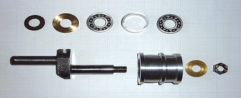 many of us might be driving around with our fan-belts too tight. The suggestion
being that a tight belt will try to climb-up the flange rather than sit nicely
on the peak of the convex pulley where it should be. Mine has definitely shown
this tendency for some time and causes one side of the belt to wear rather too
quickly. I therefore experimented with a much slacker belt and noticed an
immediate improvement in its alignment without any noticeable loss of traction
to drive the fan which might otherwise cause overheating.
many of us might be driving around with our fan-belts too tight. The suggestion
being that a tight belt will try to climb-up the flange rather than sit nicely
on the peak of the convex pulley where it should be. Mine has definitely shown
this tendency for some time and causes one side of the belt to wear rather too
quickly. I therefore experimented with a much slacker belt and noticed an
immediate improvement in its alignment without any noticeable loss of traction
to drive the fan which might otherwise cause overheating.
I recently detected some unwanted play in the top
(fan) pulley and decided it was probably time to fit new brass bushes. For some
time the fan belt had been inclined to sit against the pulley flange causing
that edge of the fan belt to fray. I have also noticed that the fan assembly is
inclined to deliver spots of grease in all directions when the engine is
running.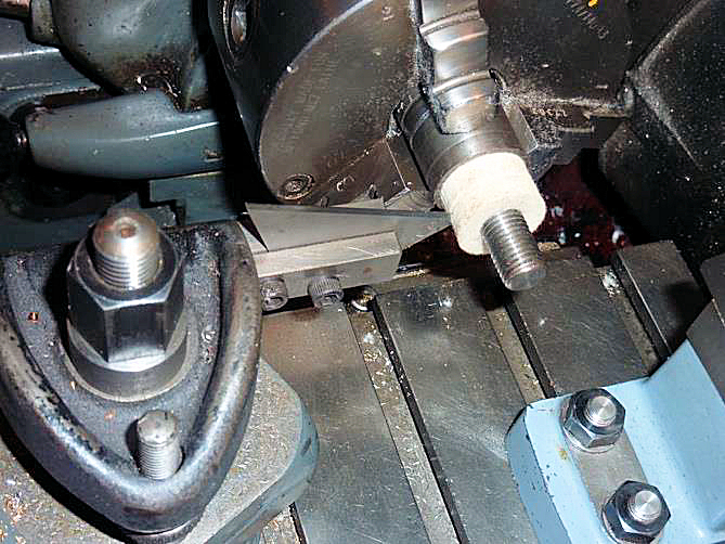
It seemed logical that the worn bushes probably
caused misalignment of the pulley which in-turn led to the worn fan-belt but the
reason for loosing grease was less clear.
A recent article in the ‘Grey mag’ mentioned the use
of ‘proper’ ball races in a fan pulley and this aroused my interest. A quick
rummage in by box of bearings soon yielded a pair of imperial ball races 1/4”
wide, ½” bore and 1.00” outside diameter. I also found a suitable chunk of
aluminium, and set about designing a new pulley.
Whilst measuring the Austin spindle, I noticed the
drilling (for conveying grease) had been made from the front and left unplugged.
This obviously lets grease reach the back of the fan, which being only a gentle
push fit on the front boss of the pulley – seemed to be a likely source of the
escaping grease. So, I decided to plug the front of this hole but not so far
back as the radial drilling that feeds the bearings. The spindle is hardened on
its outer surface but soft enough in the centre to carefully enlarge the hole to
say 5/32” Dia and tap 2BA with a relatively low percentage engagement to avoid
breaking the tap. Next, after degreasing everything, a 2BA screw was secured in
position with Loctite and cut-off flush at the front end when cured. Finally,
the cross-drilling for the nut split pin was restored.
The new pulley design was very straightforward and
based on positioning the two ball-races as far apart as possible. The Austin
felt seal housing was replicated by a light press fit brass bush to hold
everything together. Finally, the bearings are separated by a simple alloy
spacer.
The bearings were an easy push fit on the spindle and
in the new alloy pulley, so a spot of thread-lock was used to secure everything
in position, obviously taking great care to avoid getting any on the bearing
tracks.
The replacement felt seals that I have encountered
are far too wide at about ½”and need to be cut-down to a thickness of around
1/4” which means you can keep the remainder as a spare. Cutting can of course be
achieved with the kitchen carving knife but a more accurate approach, is to hold
the felt seal on a 3/8” mandrel in the lathe and cut it with a Stanley knife
blade held in a simple clamp tool as shown in the following photo.
If you run the lathe at top speed and advance the cut
very gently, the seal will only need to be a firm push-fit on the mandrel for it
to remain in place whilst cutting.
Finally, everything was sparingly greased and
adjusted to ensure a light compression of the felt seal. The pull of the fan
exerts a gentle forward axial load when running, that seems to hold the steel
insert against the brass washer at the front sufficiently well to prevent the
loss of grease. This spindle has now done well over a thousand miles, spins very
freely with no play and seems just fine. The relatively loose belt sits nicely
in the centre of the pulleys and the former source of grease spray has been
completely cured. Projects like this probably suggest that I have too much time
on my hands, nevertheless it was an interesting exercise and quite rewarding.
Fuel pump
I personally favour the use of an SU
electric fuel pump and therefore blank-off the aperture for the original
mechanical pump on the near-side of the crankcase. A neat blanking plate can
very quickly be sawn, filed and drilled from an offcut of 1/8” steel and it is
an ideal opportunity to add a bracket to carry the bottom-end of a second
throttle return spring as shown in the photo.
Article kindly reproduced from the Herefordshire A7 Club with
many thanks.