AUSTIN SEVEN ENGINE REBUILD
Article kindly
reproduced from the Herefordshire A7 Club.
Part 3 - Crankshaft & con rods
Part 1 – The crankcase,
camshaft, oil pump, rear main housing.
Part 2 - The
cylinder block and connecting rods
Part 4 -
Main Bearings
Part 5 -
Carburettors, manifolds, clutch and fan spindle
Part 6 - Flywheel
Part 7 -
Reassembly
Part 8 -
Attaching the block and cylinder head
Crankshaft
If you drive your A7 like a nervous granny, or the
engine is to be used simply as a spare, then I believe it is perfectly feasible
to retain an original Austin crankshaft, so-long as it has been carefully crack
tested and found to be sound. A common area to find cracks on two-bearing
crankshafts is the rear web just behind number four big-end journal but they can
also crack on the journals and elsewhere. However, if you are inclined to belt
along and rev the engine enthusiastically in the gears and/or seek an especially
high level of reliability from your bottom end, then a modern replacement
crankshaft is probably a good idea. This is simply because ‘two-bearing’
crankshafts tend to flex when revved hard (i.e. go round like a skipping rope)
and this can (and probably ‘will’) eventually lead to a broken crank’ through
‘fatigue’ failure. Many original Austin cranks have been whizzing around for
eighty or ninety years now, so it is mind boggling to think how many times they
may have already flexed. You might be lucky enough to have a sound Austin crank
that doesn’t need regrinding together with four beautifully matching conrods and
I can understand the temptation to re-utilise these items. However, if the
big-end journals (sometimes referred-to as crank pins) need regrinding and
consequently the conrods need re-metalling, then this significant cost might be
better spent as a contribution towards a modern crank.
The only modern crankshafts of which I have personal
experience, are the 15/16” splash-feed ones made by Phoenix Engineering and I
have found them to be perfectly satisfactory in service. My only note of caution
is that my first brand-new Phoenix crank’ was supplied with one big-end journal
10 thou’ undersize. Happily, the item was immediately replaced without any
quibble and subsequent ones have been spot-on, but nowadays I always check.
Interestingly, I recently checked the big end journals on my original Phoenix
crank’ after it had propelled a variety of A7s fairly enthusiastically for more
than 20,000 miles and there was no measurable wear whatsoever.
So how do we measure big end journals? Well, when new
or reground, the business part of a journal will start life as a precision
cylinder, i.e. sides exactly parallel and constant diameter wherever measured.
However, during its working life it will inevitably wear and because the heavy
firing stroke load from the piston/conrod is applied to a particular side of the
journal every other rotation - this will eventually cause some ovality.
Similarly, any longitudinal flexing of the crankshaft can cause journals to wear
in a conical manner. Therefore, to obtain a complete picture, we must measure
the diameter of each big-end journal at six different positions. Firstly, a
reading at each end (inboard of the fillet radius) and one in the middle, with
the measurements taken at the same angle as the firing stroke load; then a
second set of readings at right angles to the first three. The difference
between the pairs of readings will reveal any ovality of the journal at each
position and it is the maximum ovality that is of interest. Next, the difference
between corresponding readings at either end of the journal will show the extent
of any taper. Finally, a comparison of the end and middle readings will
determine the extent of any ‘barrelling’.
An ideal big-end diametric clearance for a splash
feed two bearing A7 engine is probably one or two thou’. This is where a conrod
lubricated with very thin oil, will fairly easily fall under its own weight with
the big-end bolts fully tightened. This suggests to me that an ovality of up to
three thou’, and a similar amount of end to end taper or barrel shape can all be
regarded as perfectly allowable tolerances without having to re-grind the
crankshaft. Remember, whilst it may not be frighteningly expensive to have a
crankshaft reground - the cost of the necessary conrod big-end white-metaling is
considerable and several firms nowadays are quoting lead-times of three or four
months.
Earlier, I mentioned ‘crack testing’ and I use the
Johnson and Allen two part aerosol ‘magnetic ink’ method which is
straightforward and seems to work well. It is used in the nuclear industry and
by the military so, it should be OK for Austin Sevens! After thoroughly
cleaning, polishing (with emery cloth) and degreasing the relevant areas, the
Neopaint NPT16 ‘contrast aid’ white is applied and allowed to dry, which takes
only a minute or two in a warm cosy workshop. Next, thoroughly agitate the black
Neocol B black magnetic ink aerosol to ensure full dispersion of the magnetic
particles in suspension and magnetise the item to be tested. I do this by
holding a powerful magnet against the back of the area of interest with a sheet
of paper in-between, to prevent spraying the magnet and don’t forget to keep
powerful magnets well away from your pacemaker! Finally, the magnetic ink is
sprayed onto the component surface and a careful visual inspection in good light
will reveal the presence of any crack, as a discernible black line. This method
is applicable for crack testing many other ferrous components including A7
conrods and will be referred to again in the next section. Obviously, if a crack
is detected, then the crank’ should no-longer be considered suitable for use.
Conrods
If money is no object or you are building a
racing engine, then I imagine it might be nice to have brand new conrods and
several different manufacturers now offer suitable rods for our engines.
However, I took expert advice some years ago that recommended sticking with
Austin rods for road use (including enthusiastic use) so long as they have been
carefully selected and equalised. My experience suggests this advice was sound
because I have not yet broken a conrod and many of the failed ones I have seen
were damaged for other reasons such as crankshaft failure or piston breakage.
Interestingly, I have seen terribly damaged A7 engines where the conrods have
bent but not broken which might suggest they are stronger than they look.
So how do I select conrods? I firstly check the fit
of a new gudgeon pin in the little-end, it must be a firm push fit with
absolutely no slackness, then check that the little-end pinch bolt thread is
sound. In my view, these checks are of the utmost importance because I have seen
several engines where poorly fitting gudgeon pins have caused considerable
fretting to the securing bolt. If this is left unattended, the engine is almost
certainly doomed to failure. I always use new HT bolts on assembly with internal
shake-proof washers and a touch of thread-lock - all tightened very firmly (this
will be covered in a future article).
I also file smooth and polish any potential stress
raising marks on the flanks paying particular attention to the top of the web
just below the little-end where many rods can be found to have cracks. The rods
are then crack tested in this area using the Johnson and Allen two part aerosol
‘magnetic ink’ method described earlier.
Readers with an excellent memory, will recall the
January 2014 Newsletter article containing a photo showing how A7 con-rods can
be simply checked for fore and aft bending or twist, by passing a length of
0.500” diameter ground Silver Steel through all four little ends with the rods
firmly attached to the crankshaft. For new members and those with an imperfect
memory, we have a similar photo here. The rod should be a firm sliding/twisting
fit without any binding or loose play.
Eddie assures me that slightly bent rods can be
straightened satisfactorily. Very slight adjustments by cold twisting or bending
are considered permissible. Usefully, the Dorset A7 Club website Technical Pages
show how rods can be straightened using a vice as a press.
A later article will discuss engine assembly in
detail, but it is perhaps useful here to mention that I favour being able to
pass the conrods down the bores. This usually necessitates filing away the
‘bumps’ either side of the conrod big-ends if the bores are smaller than +60.
This filing can often usefully be incorporated in the process of equalising the
weights of the four rods. At this stage, it is also useful to ensure the big-end
rods and caps are permanently marked to ensure correct positioning on
re-assembly.
Fitting conrods to crank’ journals is straightforward
in an existing engine where the journals are within limits and the white metal
in the big-ends is sound. After thorough cleaning and careful inspection of the
white-metal for cracks or other damage, the rods should be clamped in position
on the crankshaft after lubricating the journals with light oil. I keep a set of
old Nyloc nuts for this purpose and save a set of new ones for final assembly.
Interestingly, it appears there are two different depths of 5/16” Nyloc nuts on
the market and I prefer the slightly deeper ones because a socket fits more
securely without binding on the cap. So, after torqueing the nuts to the
required 18 lb ft and rotating the rod a few times to disperse the oil, check
that the rod will happily fall from the horizontal under its own weight but
without undue radial slackness. Slight (around 1/16”) fore & aft (rocking) play
at the little-end is OK in my view. If the rod seems just a little too slack, it
can be dismantled and the big-end mating surfaces rubbed on fine wet & dry paper
supported on a truly flat surface, then cleaned and reassembled. Finally, give
the big-end cap a reasonable thump via a stout brass drift and you might find
this results in a better journal fit. If the big-end still seems slack the
process can be repeated.
On the other hand, if the journal is a bit too tight,
it will be necessary to indulge in the ‘dark-art’ of bearing scraping. I say
this, because having discussed the subject over the years with a number of
experienced practitioners, I have come to the conclusion that there are several
different approaches. Anyway, the method I use (which happily seems to work) is
as follows: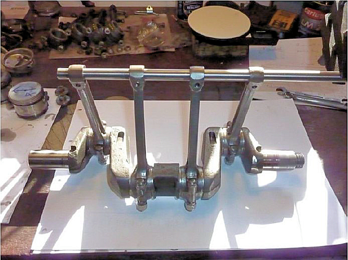
1. Prepare a ‘jig shaft’,
ground to the required journal diameter plus the required bearing clearance. In
our case say plus one to one and a half thou’ on diameter. Note: if you use the
crank journal directly instead of a jig, you will end-up with insufficient
clearance in the finished big-end bearing
2. Coat the jig shaft very thinly with engineer’s
blue
3. Clean the conrod white-metal and bring it firmly
into contact with the jig shaft and rotate it gently right around
4. When separated, the high spots on the conrod
white-metal will be marked grey/blue
5. Use a sharp scraper to carefully remove these high
spots, scraping alternately at plus and minus to the centreline of the bearing
journal
6. Repeat from Step No 2 until the blue marking
covers more than 75% of the white-metal
7. Repeat the whole marking and scraping exercise for
the big-end cap
If the above process has been
carefully carried-out and the conrod is cleaned, lubricated and assembled on the
crankshaft, it should now happily fall from the horizontal under its own weight.
Alternatively, if we are building an engine with a
new conrod/crankshaft combination, then the conrods will have to be white
metaled and machined to suit the crankshaft journals. Sadly, the days are gone
when every town had its own white-metal business and the relatively small number
of remaining providers seem rather expensive. More irritating, is that some
outfits now quote lead times of up to four months, which can be very
inconvenient. Incidentally, I’m sure readers will recall that the September 2017
issue of this Newsletter contained a useful list of white-metal specialists in
the South of England (thank you Ray).
Now, I have known people who have had white-metaling
done without specifying exactly what they want. This might be OK if the firm is
very well acquainted with Austin Sevens but I always make sure to specify the
following:
o One to one and a half thou’
diametric clearance at mid journal
o An extra thou’ or so ‘bellmouth’ at each end of the
journal
o Eight to ten thou’ longitudinal clearance along the
crank journal (Woodrow suggests as much as 60 thou’ which seems rather a lot to
me)
My approach gives a slightly
looser engine than some firms might provide if left to their own devices but is
based on advice I received many years ago from a very well respected authority
on A7s.