AUSTIN SEVEN ENGINE REBUILD
Article kindly
reproduced from the Herefordshire A7 Club.
Part 2 - The
cylinder block and connecting rods
Part 1 – The crankcase,
camshaft, oil pump, rear main housing.
Part 3 - Crankshaft & con rods
Part 4 -
Main Bearings
Part 5 -
Carburettors, manifolds, clutch and fan spindle
Part 6 - Flywheel
Part 7 -
Reassembly
Part 8 -
Attaching the block and cylinder head
Cylinder block
Happily, there still seem to be quite a few Austin
Seven cylinder blocks around but sadly they are not all in useable or
recoverable condition. Many problems with blocks can be overcome so how do we
select one that is suitable for use in an engine rebuild? Well, the first thing
I check is that there are no cracks running radially from the centre head stud
towards bores two and/or three. This fault is not uncommon and is probably
caused by severe overtightening of the head nuts - more of which in a later part
of these notes on engine assembly. The centre head stud has less supporting cast
iron than the others and is even more vulnerable if the nearby bores have been
fitted with liners. Unfortunately, if cracks are present here, I believe the
block should be consigned to the bin.
Bores
First, we need to consider the condition of
the cylinder bore surfaces and I check to see if there is any evident damage
such as vertical marks or gouges from a loose gudgeon pin or patches of very
thin wall. I have seen examples of both and such blocks need to be bored and
liners inserted before use. The process of fitting liners definitely requires
expert attention to get a satisfactorily result and even then, many builders of
sporty A7 engines avoid lined blocks.
The most obvious indicator of excessive bore wear is
the existence of a ridge above the top piston ring on the off-side of the block.
A slight ridge can often be honed away but a noticeable ridge might suggest
significant wear that requires a re-bore.
If the cylinder bore surfaces appear in good shape we
next need to check the bore dimensions and if you are the proud owner of a
proper bore gauge this is very straightforward. The rest of us probably need to
adopt a more basic approach based on measuring the clearance between a piston
and the cylinder wall. So, how do we make the necessary measurements? Well,
there are four key diameters to measure on each cylinder, the longitudinal and
transverse diameters close to the top and bottom of each bore. This can be
achieved by using a reasonably well fitting piston together with a set of narrow
feeler gauges. Clearly, it is important to use a consistent part of the piston
for this process in order to obtain comparable results because pistons often
have a variety of different diameters. The aim is to establish any ovality near
the top of the bore and compare it with that at the bottom. It is normal to find
very little ovality low down in the bores because of generally lower sideways
piston loads and better lubrication. The ovality that matters is found towards
the top of the bore and some sources recommend a re-bore if the ovality here
exceeds twelve thou’ but personally, I would be looking to re-bore the block if
this ovality was greater than say six or eight thou’.
The other feature of interest is the top to bottom
transverse taper because even at 8 thou’, this causes the ring gaps to change by
around 12 thou’ twice for each revolution of the crankshaft and I believe this
is undesirable.
If you decide a re-bore is required, it is important
to provide the pistons you intend to use and state the required piston to bore
clearance. Also, the bores should be brought to their finished dimensions by
honing which gives an excellent surface to hold oil – essential whilst
running-in.
Pistons
There are three distinct types of piston that
we commonly use in our engines –
o Cylindrical split skirt – Ideal for touring engines
with two compression and two oil control rings, happy to operate with low radial
clearance (say three thou’ on diameter) giving good control of oil consumption.
Sometimes thought to be insufficiently strong for highly tuned engines, although
I have had very satisfactory results in moderately tuned road engines
o Cylindrical solid skirt – Until recent years the
go-to piston for sports engines, again with four rings as above but needs a
little more diametric clearance – typically four or five thou’. May use more oil
but very strong
o Cut-away sports slipper – These modern pistons have
two often narrow compression rings and a single oil control ring all above the
pin. Supplied in a variety of metric dimensions and considerably lighter than
the above types therefore happier at high rev’s. The ones I have seen have
relatively narrow lands and this restricts the amount of chamfer that can be
applied at the top edge of the bore. I have no personal experience of this type
but I am told they can cause higher oil consumption
Head and manifold
studs
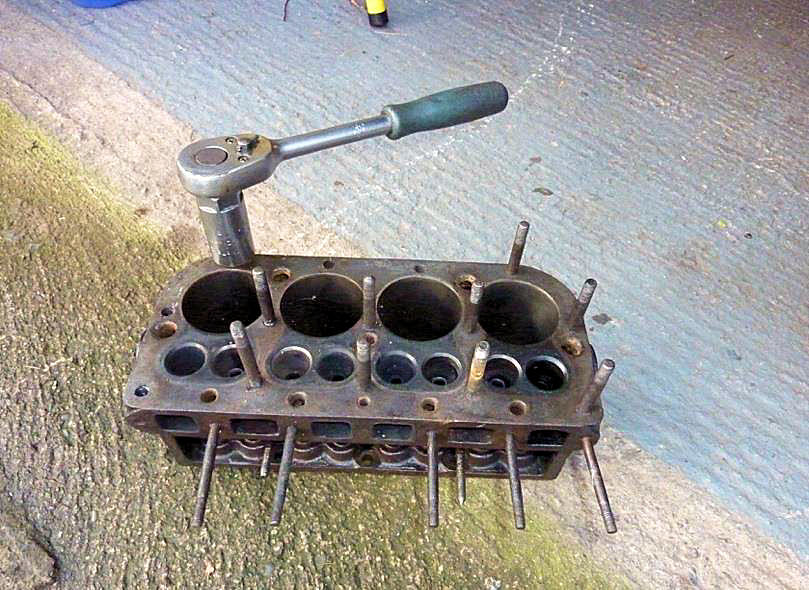
The studs in A7 blocks are often difficult to
remove. This is no surprise, because the buried ends have been in contact with
engine coolant (sometimes for many years) thus causing some inevitable
corrosion. It is highly unusual to be able to remove studs by using two nuts
locked together, unless they have recently been replaced. So, we have to
consider other options - and these range from a rather basic approach using a
good size ‘monkey’ wrench or Stilson to the various forms of proper stud
extractors.
Stilsons can be effective, especially if used as a
pair at 180 to one another but they will often damage the studs - which of
course doesn’t matter if you plan to replace them. Undoubtedly, the best method
of removing studs, is by using a proper stud extractor tool and several
different socket-drive types are available. The cheaper ones are based on an
eccentrically mounted hardened & knurled steel ring that grips the stud and they
can accommodate a range of stud diameters. However, undoubtedly the best ones
are the ‘roller cage’ type but they are rather expensive and you need a separate
one for each diameter.
In all cases, it is helpful to lean repeatedly on the
socket wrench or drive bar until you eventually feel it ‘give’. The application
of heat to the stud can sometimes help release more stubborn examples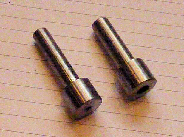 .
.
Sadly, despite all our best efforts, it is not
uncommon for manifold and sometimes head studs - to break rather than allow
themselves be unscrewed - and the break will invariably occur just below the
block surface. Now, many books tell us that in this event - you simply
centre-pop the broken stud remnant near its centre, drill a suitable hole and
use a left-hand screw extractor to remove it. I strongly suspect that these
writers are simply repeating something they have read but never actually tried
to do it themselves. I’m afraid that I have had only very limited success with
this approach.
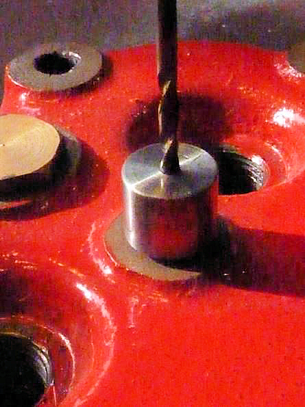
My method of removing broken studs is simple and
so-far, has always been successful. For head studs I use an old cylinder head as
the primary jig, in conjunction with a steel guide ferrule sitting in the
appropriate stud hole. The remains of the stud should be filed flat with the
mating surface if it protrudes, then the head secured in position with at least
three or four other studs & nuts before inserting and pressing-down the ferrule
and drilling-out the core of the offending stud.
Many years ago I turned-up several ferrules to suit
5/16” BSF head studs. The one shown on the left is 1/8” internal diameter and
the outside diameter is sized to fit the 5/16“ dia stud hole in the head. It is
important that the ferrule is a close sliding fit in the stud hole and the drill
a good fit in the bore, also the ferrule must reach down to the top surface of
the block. A second ferrule is then substituted to take a 5/16” BSF tapping
drill - 7/64” dia will do.
Very often, after drilling, the remains of the old
thread will fall-out or easily be coaxed out. Finally, a carefully aligned
‘second’ tap will quickly restore the thread to a usable condition.
Broken manifold stud threads can easily be repaired by
an entirely equivalent method, with appropriately sized jig ferrules and an old
Austin manifold.
I believe it is essential that all threads in the
block are in good condition, so if you are unhappy with the results of the above
process, or the threads are loose, then stepped studs are probably the answer
and they are widely available from our usual suppliers. Several other approaches
are discussed in Part 1 of these notes. In any event I would always advocate
replacing with new - any studs that do not have excellent threads.
Core plugs
If you are lucky enough to have an early
cylinder block with screw-in core plugs – you can skip this section.
Unfortunately, the more common ‘knock-in’ core plugs can appear perfectly OK but
in-fact be wafer thin due to internal corrosion. So, unless I’m sure the core
plugs have been replaced in recent years and therefore known to be sound, I
believe it is prudent to replace them with new when rebuilding an engine. It is
also much easier to clear the internal water passages of the block with the
plugs removed.
Core plug removal is normally straightforward - you
simply drive a small sharp cold chisel through the centre and lever out the
remains.
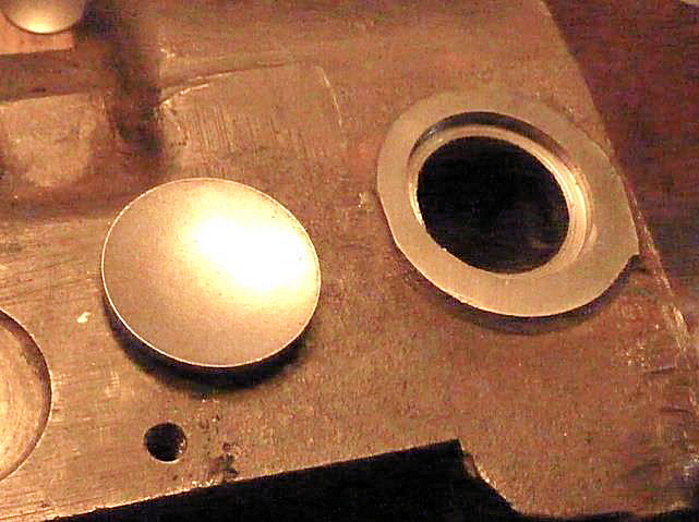
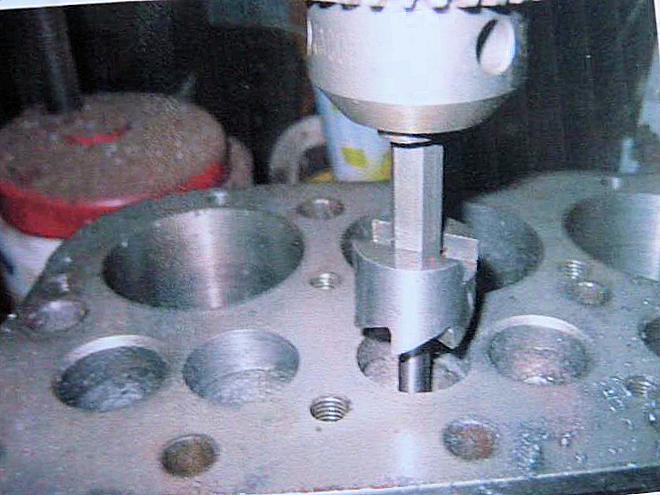
Many years ago I had a core plug fail not long after I
had replaced it, and the problem seemed to be a badly corroded housing. So,
nowadays, I always ensure the seating is thoroughly sound before assembly. The
seat shown here in the photo was machined a little deeper (there is plenty of
metal to accommodate this) using a boring head with the block clamped
upside-down on the bed of a Myford 7 Series lathe with suitable spacers. This
provided a perfect seat.
Some new core plugs have a corrosion resistant plated
surface but if this is absent, then it is prudent to apply some protection to
the inner surface. A two-part epoxy paint would be ideal. The proper
installation process for domed core plugs is well known - using a steel drift,
slightly smaller in diameter than the plug and the plug placed (concave side
down) on a thin bead of 2-part epoxy putty. Then quickly follow-up with a
whopping blow f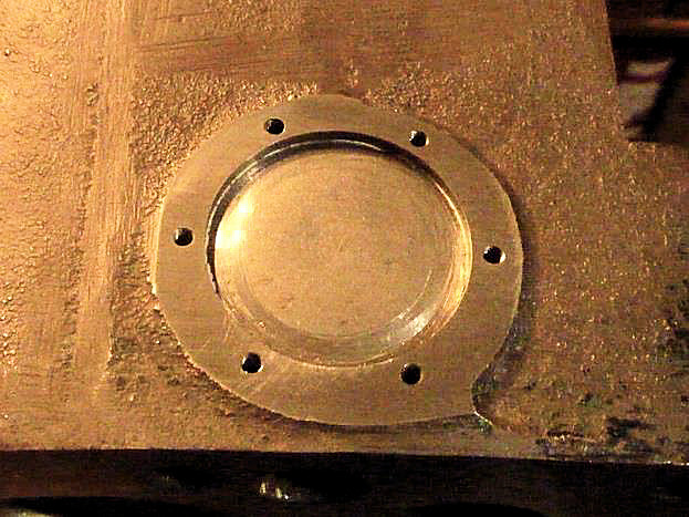 rom a heavy hammer (sometimes several) but definitely not a
series of gentle blows.
rom a heavy hammer (sometimes several) but definitely not a
series of gentle blows.
For core plugs in the block, I adopt a belt and braces
approach to completely eliminate the likelihood of any further problems by
adding steel cover-plates (see photos). The plates are about 1/16” thick -
sealed in position on a gasket smeared with Hylomar and finally secured by six
6BA x 3/8” long countersunk steel setscrews. Yes, I know what you are thinking
and I agree - this is probably completely unnecessary but I am determined never
to have another a core plug problem!
Interestingly, I recently heard of another risk averse
engine builder who used to install a second core plug on top of the first -
something I’ve never seen in the text books but certainly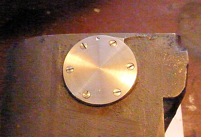 a lot quicker than my method.
Coolant passageways
The water passages in A7 blocks are often
restricted by hard rust deposits which need to be cleared if we are to avoid an
engine that boils when climbing long steep hills on sunny days. Most of this
obstructing material can be removed by poking around with a hardened blade
through the side water inlet opening but the worst affected region is likely to
be the ‘hot side’ adjacent to the exhaust manifold. Luckily, there is an
excellent article on the A7OC website dealing with this very subject, that
recommends appropriate drill sizes and depths to clear this part of the block
(and head). It is also important that when the manifold studs are installed,
they do not protrude into these newly cleared areas.
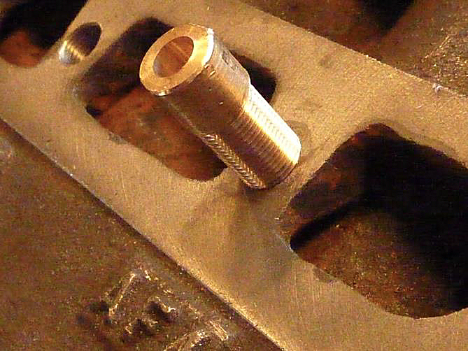
The cast iron ‘bridges’ supporting the side water
inlet mounting studs are often badly corroded. If the ‘bridges’ are largely
intact but the 5/16” BSF stud hole threads are in poor condition, it is often
possible to drill and tap say 7/16” x 26 TPI and turn-up a pair of bushes (I use
bronze) threaded externally to suit and internally 5’16” BSF as shown in the
following photos.
The bushes are fixed in position with high strength
Loctite and after curing – cut and filed flush with the flange surface as shown
in the photo on the left.
I have used this method several times and it has
proved entirely satisfact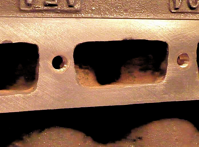 ory. However, if the ‘bridges’ are badly damaged or
non-existent and you are desperate to retain your favourite block – then all is
not lost, because laser cut stainless steel repair plates are now available.
ory. However, if the ‘bridges’ are badly damaged or
non-existent and you are desperate to retain your favourite block – then all is
not lost, because laser cut stainless steel repair plates are now available.
There is an excellent article by Colin Danks on the
Bristol A7 Club Website …. http://www.ba7c.org/ (with photos by Terry Griffin)
that describes in detail the fitting of a repair plate.
In essence, the plate is fixed in position with
stainless steel countersunk set-screws on a gasket with sealant. The plate is
not really thick enough to thread for the 5/16” studs, so nuts (preferably also
stainless) need to be silver ’soldered’ on the back. Any remaining ‘bridge
remnants obviously need to be sawn off to clear these nuts. Austin’s
standard ¼”diameter manifold studs have always struck me as being slightly
flimsy - so, I make mine 9/32” diameter, threaded BSF and make nice beefy 7/16”
AF brass nuts to suit. Much better engineering in my view and I like to think
that Sir Herbert wouldn’t be too disapproving!
Block to crankcase
fixings
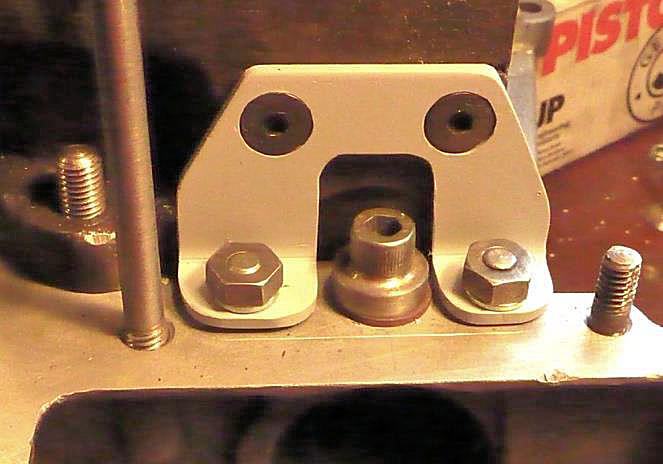
The cylinder block is attached to the crankcase by
eight 5/16” BSF studs and for normal use with single valve springs and a
standard camshaft this is probably adequate so long as the threads in the
crankcase are in good condition. However, if like me you like your engine to
develop a little more power, you might employ a camshaft that gives a little
extra valve lift and to fully exploit its potential, you will frequently want to
employ high engine revs which calls for double valve springs. All this suggests
to me that those eight studs might appreciate a little help especially in the
areas at either end of the camshaft. I have seen a variety of solutions over the
years that include bolts running from inside the crankcase to different patterns
of external brackets some of which struck me as decidedly clumsy.
My approach is to attach simple mild steel brackets at
the front and back of the engine above the line of the camshaft attached to both
the block and crankcase. Although there is not a great deal of space to
accommodate such brackets (especially at the front of the engine) or depth of
aluminium to secure them, it is possible with care to make and fit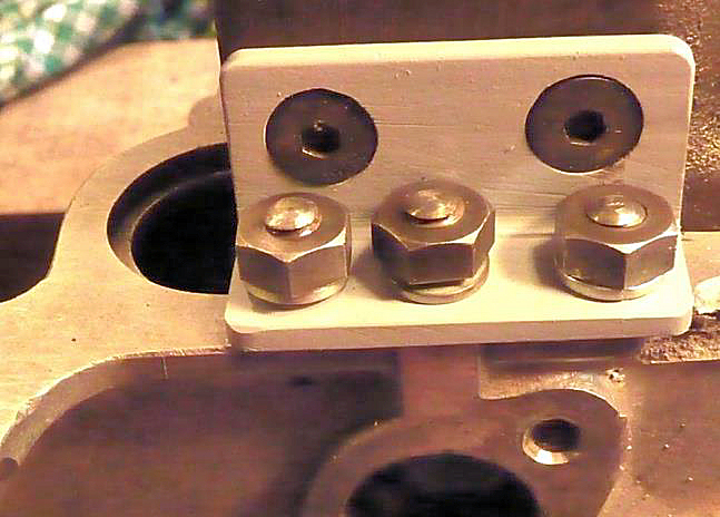 suitable items. The examples shown in the following photos are attached to the
block by a pair of 5/16” BSF countersunk hex drive setscrews secured with
threadlock and to the crankcase by ¼” BSF studs and nuts. The stud spacing of
the rear bracket looks somewhat irregular but they were positioned to maximise
the available depth of crankcase material.
suitable items. The examples shown in the following photos are attached to the
block by a pair of 5/16” BSF countersunk hex drive setscrews secured with
threadlock and to the crankcase by ¼” BSF studs and nuts. The stud spacing of
the rear bracket looks somewhat irregular but they were positioned to maximise
the available depth of crankcase material.
A very approximate calculation suggests that each
bracket provides a ‘holding-down’ capacity at least equivalent to an additional
5/16” block/crankcase stud. In any event, it seems to work because I have no oil
leakage from the block/crankcase joint despite frequently using high engine
rev’s.
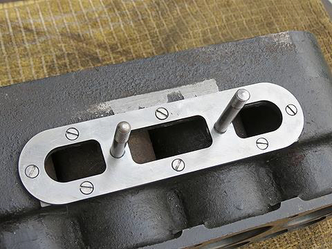
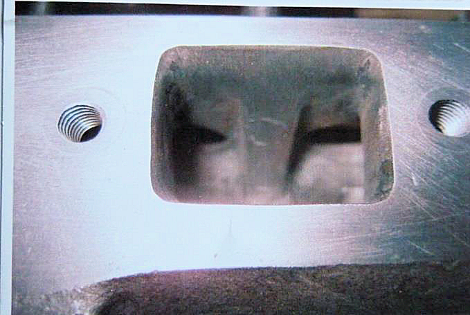
Ports
A great deal of information regarding optimal
side-valve port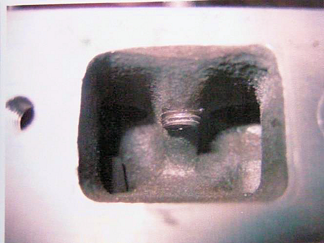 geometry for high revving
 racing
engines, can be found in the 750 Club Companion and Special Builders Guide. Much
of this is very interesting reading but for a lively road-going engine, I
conclude that generally smooth passages devoid of any sharp steps is all we
need. Depending on the choice of manifold, this probably means removing some
metal from the outer ends of the ports and making sure the gasket does not
intrude. The bottom end of the head stud immediately over the Siamese inlet
ports can also usefully be smoothed-off as shown in the following photos.
racing
engines, can be found in the 750 Club Companion and Special Builders Guide. Much
of this is very interesting reading but for a lively road-going engine, I
conclude that generally smooth passages devoid of any sharp steps is all we
need. Depending on the choice of manifold, this probably means removing some
metal from the outer ends of the ports and making sure the gasket does not
intrude. The bottom end of the head stud immediately over the Siamese inlet
ports can also usefully be smoothed-off as shown in the following photos.
I believe there is no advantage in polishing the
ports, a smooth matt finish being more desirable, although this is not the case
with the cylinder head and piston crown where a polished finish will offer some
advantage.
Valves
If the valves can be wobbled in their guides
to any extent, I always replace the guides with new.
 The
old ones can easily be driven downwards for removal with a suitable stepped
drift and new ones inserted the same way, preferably with a copper washer
protecting the top surface of the guide. Better practice of course would be to
use a simply made threaded ‘puller’. With the new guides in place, it is useful
to check that a clean valve slides freely but without any play. If the valve is
tight, careful use of an expanding reamer will soon ensure a good sliding fit.
Incidentally, the guides should be positioned so that the top surface projects
3/32” into the valve port.
The
old ones can easily be driven downwards for removal with a suitable stepped
drift and new ones inserted the same way, preferably with a copper washer
protecting the top surface of the guide. Better practice of course would be to
use a simply made threaded ‘puller’. With the new guides in place, it is useful
to check that a clean valve slides freely but without any play. If the valve is
tight, careful use of an expanding reamer will soon ensure a good sliding fit.
Incidentally, the guides should be positioned so that the top surface projects
3/32” into the valve port.
The valve seat should be re-cut after installing new
guides, removing as little material as possible noting that standard seats are
45 and a seat width of around 0.10”is typical.
It seems Sir Herbert believed that standard size
valves were fine for A7 engines - and for modest power requirements, I’m sure he
was right. On the other hand, if you seek a little more oomph and are willing to
run the engine at higher revs, then fitting larger inlet valves is pretty
straightforward. A 1.00”dia cutter with a 0.275” dia mandrel to fit the valve
guide is run at slow speed to cut a depth of around 5/8” and the bottom of the
cut blended into the port with a rotating grind stone. A new valve seat is then
cut in the top face.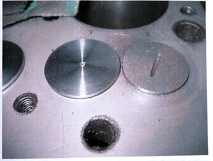 This can with advantage be cut at 30 and only a narrow seat of say 1/16” width
is needed, because the incoming mixture tends to keep the valve and seat a good
deal cooler than the exhaust.
This can with advantage be cut at 30 and only a narrow seat of say 1/16” width
is needed, because the incoming mixture tends to keep the valve and seat a good
deal cooler than the exhaust.
Large inlet valves are available from our suppliers
and the heads are typically 1.142” (29mm)dia. I make sure there is a clearance
between enlarged inlet and standard exhaust valves on assembly of around 10 thou
and this can be achieved by carefully turning down the inlet valve head in the
lathe.
Incidentally, whilst using the lathe, the top edges of
enlarged inlets can usefully be slightly rounded to improve gas flow into the
combustion chamber. This can be seen on the top valve in the photo also the much
wider seat on the lower standard size exhaust valve.
I definitely favour valves secured with cotters rather
than pins because many years ago, I had a pin shear. I also use double valve
springs with cotter cups to suit, which allows the engine to achieve high rev’s
whilst eliminating the chance of any valve bounce.
Chamfer to top edge of
bore
If you consider the many changes of direction
of the gas path from the inlet port, up past the valve, across into the
combustion area then back out, it will be no surprise that some rounding of the
top right-angle edge of the bore will help matters. The theory of fluid dynamics
suggests that even a very small rounding will make quite a difference. The key
limitation is of course the position of the top compression ring at TDC and this
is determined by a trial engine assembly then allowing say an extra 20 thou’ to
be safe. Also, the width of any chamfer is obviously limited by the head gasket
dimensions.
Cylinder head
The low compression Austin cylinder head is
not usually associated with performance and often believed to respond poorly to
skimming in an attempt to extract more power by increasing the compression
ratio. Nevertheless, I have observed one or two early lightweight Sevens
performing remarkably well with skimmed low compression heads. Received wisdom
tells us that the higher compression (originally 5.8:1) ‘1937’ head enjoys a far
superior combustion chamber shape and in my experience it does seem to offer
more power, although I have never tried a skimmed low compression head.
Original Austin cylinder heads have now been around
for rather a long time and it is sometimes difficult to tell whether they have
been skimmed and if so, by how much. There is an excellent article on this
subject to be found on the Bristol A7 Club Website but it can be useful to know
that original heads were believed to measure within 10 thou of 1.50 inches in
height when they left the factory. Bill Williams also cautions us not to take
the compression ratio (CR) above 7 to 1 and don’t forget that increasing the
bore will also increase the CR. I will return to this subject in the final part
of these notes on engine assembly, because the compression ratio is also
affected by the thickness of the head gasket.
A variety of alloy heads are available for our engines
but I only have first hand experience of the Speedex and Supalloy offerings.
Both seem to provide a power output similar to the 1937 Austin head but have the
advantage of being considerably lighter. However, if you aspire to compete in
VSCC events, you might find you are restricted to the Watmough Hewitt head with
18mm plugs. I have heard fears that alloy heads distort and regularly need
re-facing but this is most definitely not my experience. Just for the record, I
have been using a Supalloy head (estimated CR of around 6:1) for over ten years
without any problems.
Starter housing
When fitting the starter housing , you must
fit the locating dowels because these take the strain from the mounting set pins
. The mounting set pins will always work loose if the dowels are missing , there
is quite considerable torque reaction when the starter is actuated thus the
importance of the dowels.
There is another reason for fitting these dowels, they
help to maintain correct alignment between starter teeth and flywheel teeth.
Because the starter housing is mounted directly to the
crankcase, the set pin threads are machined into soft aluminium so will quickly
wear if there is movement between housing and crankcase, to effect a repair to
possible damaged threads will always involve engine removal .
Eddie Loader