As mentioned in Part 1, there are two possible locations for the starter motor on two bearing A7 coil engines and this means two different flywheels. The early configuration with the starter in the cabin alongside the gearbox incorporated the starter ring-gear on the clutch cover plate whilst later models had the ring gear shrunk onto the front of the flywheel.
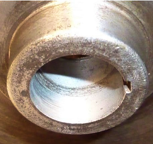
Fortunately, Austin Seven flywheels are decidedly robust and seem plentiful, but how do we select a good one? Well, my view is that the taper is of primary importance, because it is absolutely essential that we achieve a good fit on the crankshaft. Flywheels and crankshafts in Austin Sevens occasionally display an uneasy relationship by tending to come loose. Austin may have become aware of this, because whilst the taper in early flywheels took the form of a continuous truncated cone, the later ones had an annular relief halfway down the taper which seems to make it easier to achieve a perfect match with the crankshaft taper.
This match is achieved by holding the crank’ firmly in the vice (soft metal facings in place please) and coating the taper with a thin film of fine grinding paste, then without the woodruff key – rotate the flywheel a few times whilst applying some pressure to push it onto the crank’ taper. If you are lucky, when the taper surfaces are thoroughly cleaned you will see a dull ground area covering the whole contact area. If not, I simply repeat the process until a contact area of at least 80% is achieved.
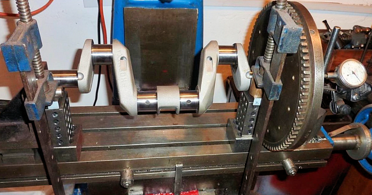
Whilst we are messing about with grinding paste, it is a good idea at this stage to test the run-out of the flywheel near its rim. Some engine builders accept a run-out of up to fifteen thou’ and others don’t even bother to check it at all but I like to get it to around five thou’ or better, because it all contributes to a smooth running engine and also gives the clutch an easier ride. Checking flywheel run-out is very straightforward once the crank has been installed in the engine but making any adjustments with grinding paste so close to the rear main bearing fills me with horror. There are endless alternative approaches, but I simply clamp two shallow vee blocks (supported at an appropriate height) on the bed of the vertical milling machine, to support the main bearing journals. A further ‘stop’ is clamped in position to bear on the front of the crankshaft. The mill table provides an ideal firm flat surface and
 happily accepts a magnetic mount for the dial gauge. The set-up I use can be
seen in the photo ….
happily accepts a magnetic mount for the dial gauge. The set-up I use can be
seen in the photo ….The flywheel is firmly tightened onto the crank with the woodruff key in position and the assembly is rotated slowly by hand whilst keeping it pushed firmly against the ‘stop’ clamped at the front end of the crank’. Obviously, the face of the flywheel needs to be perfectly clean where the dial gauge runs, nevertheless it is not uncommon to get erratic readings with very slight rotations of the assembly. So, I tend to take an average of several readings close to four (north, south, east & west) positions of the rim.
Incidentally, it is important that the Woodruff key is both a firm (gentle tap) fit in the crankshaft slot and also there is no slack in the flywheel groove. However, it is even mor
 e
important that when assembled, there is a slight but definite clearance between
the top surface of the key and the groove in the flywheel. This can be checked
by careful measurement or tested with a small shim. Unwanted interference here
has been known to be the cause of loose flywheels.
e
important that when assembled, there is a slight but definite clearance between
the top surface of the key and the groove in the flywheel. This can be checked
by careful measurement or tested with a small shim. Unwanted interference here
has been known to be the cause of loose flywheels.If any adjustment is required, the flywheel is marked where the run-out is greatest and removed from the crank. Then it’s back to the grinding paste but this time, the flywheel rim is rotated back and forth (without the woodruff key) whilst pushing firmly to correct the ‘high’ area. You need not be too concerned about over-correction, because it takes several minutes to correct a tiny amount of run-out with fine grinding paste. This process of cleaning, tightening and removal with the flywheel puller can be rather time consuming and require multiple iterations. Nevertheless, when friends and family enquire about your flywheel run-out, it is very satisfying to be able to say ‘it’s negligible’!
Loose Flywheel
Loose A7 flywheels can also be caused by a lack of clearance between the flywheel boss and the centre of the rear main bearing, when fully tightened. This clearance needs to be small enough to nip the oil thrower indents to prevent it rattling around loose but large enough to prevent it being squashed flat. If the indents are completely flattened, the flywheel taper might not fully and firmly engage with the taper on the crankshaft. With the flywheel fully tightened in position, we need an absolute minimum clearance of 0.906” this being the depth of the rear main bearing centre race of 0.872” plus the thickness of the fully squashed oil thrower indents of 30 thou’ plus a small allowance of say 4 thou. The thickness of new unsquashed indents is typically around 70 thou so the maximum clearance we should allow is 0.932”, which assumes around 10 thou of squashed oil thrower indents. In the unlikely event the clearance is greater than this, then the thrower indents will need to be enhanced. On the other hand, (and much more likely) if the clearance is too small, then an appropriate amount must be machined from the front of the flywheel boss. I have read a number of articles that glibly suggest mounting A7 flywheels in a lathe and carrying-out such operations but not many of us own a lathe big enough to do this. Never mind, material can easily be end-milled or fly-cut from the front of the boss in a domestic size milling machine with the flywheel clamped flat on the table. This should be followed by lightly dressing the front edge of the boss with a smooth file to remove any roughness.
Oil Seal
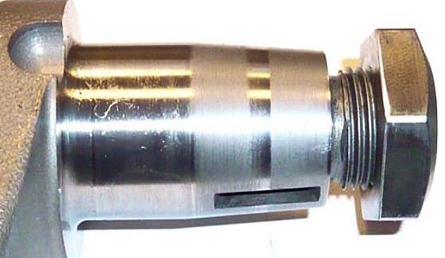
An oil-tight Austin Seven engine is a thing of great beauty, so I like to pay attention to the oil retention arrangements at the back of the engine. Rather than Sir Herbert’s reverse oil scroll groove which in many engines is rather worn. I favour one of the quite reasonably priced modern oil seal plates machined to take a modern lip seal. However, these are only effective if the seal engages correctly on the flywheel boss and the boss itself has a suitably smooth finish. Incidentally, these lip seals are available in either ‘touring’ or ‘high speed’ versions and if you are inclined to rev your engine freely – then the later item seems a logical choice. However, these sporty seals are made of ‘Viton’ and are about three times the price.
The seal position can usually be adjusted a little if necessary by moving it forward or backward in its housing and this is usually sufficient to ensure the seal sits close to the middle of the periphery of the flywheel boss.
Flywheel Boss
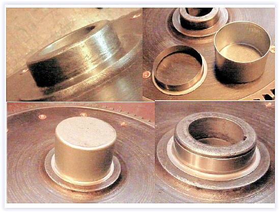
Next we should examine the finish on the boss itself and if unable to achieve a smooth shine with fine wet & dry, I fit a thin wall sleeve such as an SKF Speedi-Sleeve. Most coil engine flywheel bosses are nominally 1.872” diameter and the appropriate SKF Speedi-Sleeve Stock No is 99188 which has an overall depth of 0.415” and fits diameters of 1.872” to 1.879”. These sleeves are easy to fit using the tool supplied but the boss must not have any rough high spots because they would ‘show-through’ the very thin wall of the sleeve. The following photos show a flywheel boss that needed a sleeve, the sleeve kit, the sleeve knocked in position with the metal ‘cup’ tool and finally the sleeve in position on the flywheel boss.
Flywheel Taper
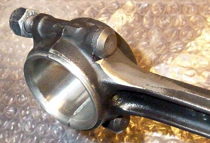
Earlier, we took a great deal of time and trouble to ensure the flywheel was correctly seated on its taper whilst properly supporting the oil thrower. However, several engine builders have raised the question of whether a thrower is required at all if we are fitting a modern lip seal. The argument being that a modern spring loaded seal should comfortably resist A7 crankcase pressures and might last longer through better lubrication if fully exposed. However, it seems to me that the thrower (which should of course be assembled with the dish side facing away from the engine) tends to fling oil into the seal, so the seal rubbing surface is probably adequately lubricated. Therefore, so far, I have not had the courage to leave-out the thrower but if anyone reading this has already tried – then our Editor would be very pleased to hear from you.
Starter Ring Gear
Another flywheel feature worthy of consideration is the condition of the starter ring gear. It has always surprised me how successfully A7 starter motor pinions can engage with quite chewed-up ring gears but if the teeth are really badly damaged, then a new gear is probably required. I have always entrusted ring gear replacement to specialists and the costs have always seemed reasonable. Usefully, new ring gears can often improve the balance of an engine.
Balancing
It is not uncommon for A7 engines to run perfectly smoothly without ever having been balanced and I
 imagine this is more likely to be the case if the engine is treated gently.
However, if you are inclined to belt your engine, then I believe you are more
likely to have a smooth rewarding experience if the rods are carefully equalised
and the crankshaft/flywheel/clutch cover plate assembly has been dynamically
balanced. On several occasions, I have found these items to be alarmingly
out-of-balance even when using a Phoenix crank’, so nowadays, I always have my
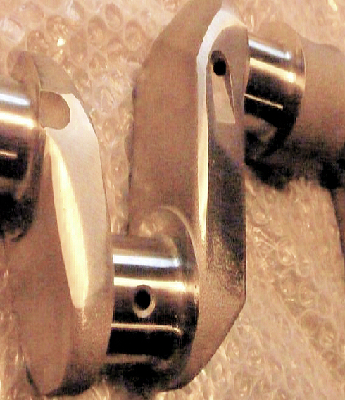
engines dynamically balanced. The following photos show how much metal can
require removal to achieve a well-balanced bottom end ….
imagine this is more likely to be the case if the engine is treated gently.
However, if you are inclined to belt your engine, then I believe you are more
likely to have a smooth rewarding experience if the rods are carefully equalised
and the crankshaft/flywheel/clutch cover plate assembly has been dynamically
balanced. On several occasions, I have found these items to be alarmingly
out-of-balance even when using a Phoenix crank’, so nowadays, I always have my
engines dynamically balanced. The following photos show how much metal can
require removal to achieve a well-balanced bottom end ….Some owners of sporty A7 engines have their flywheels lightened and whilst this might be an advantage in a racing scenario, I have never dabbled - probably due to cost if I’m honest. In my experience, a modestly tuned and well set-up A7 engine will pick-up pretty quickly and reasonably rapid gear changes are quite achievable. I have therefore convinced myself that until someone gives
 me a whopping great lathe – an unmolested, reassuringly heavy original flywheel
will be just fine - and maybe even contribute to a smooth running engine.
me a whopping great lathe – an unmolested, reassuringly heavy original flywheel
will be just fine - and maybe even contribute to a smooth running engine.