 Please note that modern slipper pistons offer limited scope for this
modification because, as mentioned earlier, they have a shallower land above the
top ring than most ‘full skirt’ pistons.
Please note that modern slipper pistons offer limited scope for this
modification because, as mentioned earlier, they have a shallower land above the
top ring than most ‘full skirt’ pistons. AUSTIN SEVEN ENGINE REBUILD
Article kindly reproduced from the Herefordshire A7 Club.
PART 7 - RE-ASSEMBLY
Part 1 – The crankcase, camshaft, oil pump, rear main housing.
Part 2 - The cylinder block and connecting rods
Part 3 - Crankshaft & con rods
Part 5 - Carburettors, manifolds, clutch and fan spindle
Part 8 - Attaching the block and cylinder head
ENGINE RE-ASSEMBLY
Numerous books and articles have been written telling us how to assemble an Austin Seven engine and the ones I have found most helpful are Woodrow’s A7 Manual, Notes from a series of lectures by Jack French - Pages 126 et seq of the 750 Club’s A7 Companion, some elements of Chapter 2 in Bill Williams book ‘A7 Specials’ and pages 37 to 42 of the Practical Classics ‘Austin Seven Briefing’. The following notes are not intended to be a complete start-to-finish treatise on A7 engine assembly but rather a collection of points that I believe are important
.
FITTING THE
CRANK
Assuming the
crankcase and the front main bearings have been prepared, we can start by
fitting the crankshaft. The crank is threaded through the rear main bearing
aperture after the front of the crankcase has been thoroughly warmed-up, for
which I use a hot air gun. With the crankcase sitting vertically on its
bell-housing and the tail of the crankshaft supported in roughly its final
position on a hardwood block, the front angular contact bearings can be
carefully tapped into position (over the front of the crankshaft and into the
front main bearing housing) with the faces marked ‘thrust’ facing one-another
and all surfaces lightly oiled. If everything is spotlessly clean, the crankcase
hot to the touch and things reasonably well-aligned - the bearings can now be
coaxed into position using a brass drift and a medium weight hammer without the
need for any heavy blows. If you are too heavy-handed, you risk damaging the
retaining lip in the crankcase or the balls marking the races which could give
the engine an irritating rumble from day one.
The bearings should
carefully be driven fully home against the retaining lip – then, if you have
used the correct bearings (and spacers if required), the outer front race will
protrude a little above its housing. The bearing retaining plate can then be
fixed in position, together with its locking tab washers.
The front crankshaft
timing gear is then slipped into position (boss first) taking care to ensure
that the small woodruff key stays in position. A new tab washer follows and I
find it useful to first bend-up the tab extremity a little with a pair of
pliers. This doesn’t affect the fitting of the ‘starting’ nut but greatly
facilitates locking the tab when the time comes.
With the front
bearing retaining plate secure and the starting dog nut firmly tightened (but
the tab not yet locked), we have a seriously exciting moment. Because, by trying
to waggle the free rear end of the crankshaft by hand, we will immediately
discover whether the A/C bearings at the front of the engine (whether brand new
or adjusted as described in an earlier Part have the correct pre-load. There
should be no detectable ‘waggle’.
It is useful at this
stage to temporarily pop the cylinder block into position to check that the
big-end journals of the crankshaft align centrally with the cylinder bores. This
will confirm whether the combination of crankcase, front A/C mains and spacers
(if any) is correct. Assuming everything is in order at the front, we can direct
our attention to the rear main bearing. It is essential that the inner race is a
good fit on the crankshaft and that the bearing housing is not damaged or
distorted. If the housing is warmed-up it will help us drive (or press) the
outer race fully-home, this assembly can then be fitted into the back of the
crankcase - sandwiching the thinner of the two gaskets (smeared with a thin coat
of Blue Hylomar or similar) making sure the housing and gasket holes align
correctly with the tapped holes in the crankcase. At this point we must also
check that the oil drain hole is correctly aligned with the return drilling in
the crankcase and free of any stray sealant. The inner race can now be drifted
into position firmly against the rear flange of the crankshaft taking care that
the rollers enter the outer race happily without tipping or binding. The oil
thrower (with appropriate indents) is now positioned with the dish side facing
away from the engine. The oil retention plate follows, and my preference is for
one that contains a modern lip-seal. This sits on the thicker of the two gaskets
(again with a thin smear of sealant) and the whole lot then secured in position
with the four shallow head set screws and locking tab washers. Shallow head
screws are important, because normal size heads would foul the flywheel when
fitted.
That completes the installation of the crankshaft except for locking the front timing pinion tab washer which will follow later.
FITTING THE BLOCK
Our cylinder blocks
have been around for over eighty years and may well have had their top surfaces
skimmed at some stage – so, I believe it is vitally important to check the
clearance above the pistons before continuing with final assembly.
This trial assembly
obviously requires that the pistons be attached to their con-rods but there is
no need at this stage to fit either the little-end bolts or piston rings and I
use an old set of big-end bolts and nuts.
For two-bearing A7
engines, if either the top face of the cylinder block has been machined, or
significant lapping has been carried out on the top surface of the crankcase,
then a trial assembly will reveal whether there is sufficient clearance over the
pistons. This may not be critical if you plan to use an early low-compression
head but essential if you aspire to a high compression top-end, such as a ‘1937
A7 head’ or one of the proprietary (often aluminium) varieties. It seems that A7
engines when new had a clearance above the piston crown at TDC to the top
surface of the block of around five to ten thou’. This, together with a good old
fashioned Copper/Fibre head gasket of about fifty thou (compressed) thickness,
would allow a standard Austin two-bearing crankshaft to rev to around 6,000 rpm
(for a short while anyway) without pistons two and three hitting the head due to
crankshaft whip. Unfortunately, some modern copper/asbestos head gaskets are as
thin as thirty thou’ so the clearance over the pistons needs to be assessed and
corrected to between five and ten thou’ if necessary. This is most easily
achieved by adding an aluminium shim plate of appropriate thickness between the
block and the crankcase. These shim plates are available in various thicknesses
of typically 10 and 20 thou’. Incidentally, they may appear to be a regular
pattern that can be fitted either way up - but one I used recently was a much
closer match to the top of the crankcase one-way rather than when flipped over.
Definitely worth checking.
Another option for
increasing the clearance above your pistons, is to machine a small amount off
the piston crowns. Whilst this might be perfectly feasible for earlier type
pistons - it is inadvisable in my view for modern slipper pistons, because they
have only a very shallow land over the top ring. Anyway, the whole idea of
machining pistons and then making sure they are exactly identical in weight has
never really appealed to me. Happily, crankshaft whip is believed to be less of
a problem with modern replacements, so the proud owners of these desirable items
can perhaps get away with a lower clearance than suggested above.
One other influence
here is whether or not a gasket is used between block and crankcase and if so,
what type. Well, for years I used the traditional paper gasket typically having
a compressed thickness of only a few thou’, assembled with a thin smear of Blue
Hylomar on each surface and that was generally fine. However, I now take great
care to ensure the mating surfaces of the block and crankcase are both
beautifully flat and carefully de-greased, then using only a thin smear of
Hylomar has proved very successful, with no oil leaks and the block holding-down
nuts staying tight. Of course, if you are introducing a shim plate, you will
need to apply sealant to both sides. I did assemble one engine with a silicone
gasket and whilst it certainly remained oil-tight, I noticed that the
holding-down nuts regularly needed to be tightened. It seemed the silicone was
gradually migrating under load despite having been assembled dry on de-greased
surfaces as per the instructions. The problem was that the tightening affected
the tappet clearances which consequently needed adjustment.
As mentioned in
earlier Parts, the theory of fluid dynamics suggests that the movement of gasses
into and out of the engine will be improved if the sharp edge of the block
leading into the bore is slightly rounded. The key limitation is of course the
position of the top of the upper compression ring at TDC and this can usefully
be determined during our trial assembly. I then allow, say, an extra 20 thou’ to
be safe. The width of any chamfer or rounding should obviously be limited to
correspond with the head gasket dimensions and all four chamfers should be
identical. Please note that modern slipper pistons offer limited scope for this
modification because, as mentioned earlier, they have a shallower land above the
top ring than most ‘full skirt’ pistons.
Having made sure
that our pistons won’t collide with the head and created any required chamfers –
we can now get-on and complete the engine.
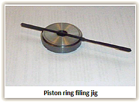
Piston ring gaps
New piston rings are
normally supplied to fit the bore size with virtually zero clearance, so, we
usually need to file away a small amount of material to obtain the desired gap.
I do this using the
simple jig shown
in the photo
that has an accurately cut, centrally located vertical groove which is a snug
fit to a thin flat ‘Swiss’ file. The ring is held on the jig by hand and
squeezed to close the gap gently against the file. Proceed carefully with the
filing because rings are fragile and it’s very easy to remove more material than
intended.
Ring gaps are
conveniently assessed by supporting the ring on an old piston to ensure it sits
exactly square to the bore - then removing the piston and measuring the gap with
feeler gauges. The gap is measured at both positions of interest and the
measurements should be virtually identical.
There are two
fundamentally different approaches to assembling A7 engines. The conventional
method described in many books is to fit the piston & conrod assemblies in the
block with the oil baffles in-place on the rods, then bring the block and
crankcase together on the gasket if using one. However, I find this a right
fiddle and very much favour ensuring that the conrod part of the big-ends can
pass down the cylinder bores, which makes things much more straightforward.
Con-rods & pistons
Pistons can now be
fitted to the con-rods remembering that it is essential the gudgeon pins are a
firm sliding fit in the little-ends whilst not binding at all in the pistons.
The grooves in the pins must be carefully aligned to admit the little-end screws
and this can usually be achieved by hand, although Woodrow shows a suggested
tool that can sometimes help. I always use new HT little-end screws with
internal shake-proof washers together with a medium strength Loctite on
degreased threads but care must be taken to prevent any Loctite from finding its
way onto the gudgeon pin.
Little-end screws
often have fairly shallow (often slightly domed) hexagon heads and must be very
firmly tightened. This is greatly facilitated by using ‘buttons’ such as those
described in Woodrow to hold the pistons in the vice and I use a high quality
combination spanner with one face ground flat to maximise engagement with the
hexagon head of the screw. Interestingly, there is much better access to the
little end screw with ‘slipper’ type pistons.
Bill Williams is one
of the few sources of information that tells us that the little-end bolt heads
should face towards the off-side of the engine although this might be Longbridge
tradition rather than cunning design. Also, if you are using split-skirt
pistons, the split should face towards the camshaft (near-side), but this is
more obvious from first principles.
The piston rings can
now be fitted to the pistons and most suppliers provide us with clear
instructions. However, this is not always the case with some products from the
far-east. For example, a recent set of slipper pistons with one oil control, one
(dark finish) scraper and one (shiny) compression ring were supplied without any
instructions. The rings were helpfully marked to show which surface faced ‘top’
but the two top rings shared identical dimensions and it was unclear which went
where. It turns-out that the shiny one was the compression ring and should be
fitted in the top groove.
Fitting rings is a
straightforward process, but care is needed to avoid scratching the piston lands
and sliding the rings over thin brass shimstock can help. Interestingly, modern
pistons with narrow rings (thus lower contact areas) are designed to give lower
bore contact pressures than their conventional counterparts. This has the
obvious advantage of reducing friction and happily, makes them a little easier
to fit.
FITTING THE CAMSHAFT
If your timing gears
have enjoyed a happy former life in the crankcase yo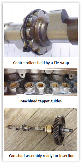 u plan to use, we can skip
the next step. Otherwise, it will be necessary to select a pair of suitable
gears. If you are lucky, there will be an original Austin dimension stamped at
the top front of the crankcase that indicates the departure from standard of the
dimension between the camshaft and crankshaft bore centrelines. You will be even
luckier if you can find a pair of timing gears that correspond, also,
unhelpfully, some gears are unmarked. In this case it will be necessary to mix
and match from a collection of spares from your own and your friends spares,
avoiding badly worn specimens if possible and obtain satisfactory meshing by
trial and error.
u plan to use, we can skip
the next step. Otherwise, it will be necessary to select a pair of suitable
gears. If you are lucky, there will be an original Austin dimension stamped at
the top front of the crankcase that indicates the departure from standard of the
dimension between the camshaft and crankshaft bore centrelines. You will be even
luckier if you can find a pair of timing gears that correspond, also,
unhelpfully, some gears are unmarked. In this case it will be necessary to mix
and match from a collection of spares from your own and your friends spares,
avoiding badly worn specimens if possible and obtain satisfactory meshing by
trial and error.
We must now set the
longitudinal clearance of the front camshaft bearing. This is achieved on the
bench by bolting the cam pinion in place and measuring the clearance with a
feeler gauge. We are aiming for a clearance very close to two thou’. This is
important, because a larger clearance will almost certainly cause the engine to
emit a rumble. It is easy to reduce this clearance by rotating the camshaft gear
on its taper with a little fine grinding paste, then scrupulously cleaning
everything and trying again. If, however, there is insufficient clearance, a
very small amount can be removed from the back face of the gear in the lathe.
If the rear camshaft bearing has been removed for inspection and cleaning, it should now be refitted into the back of the crankcase on a thin gasket with a touch of sealant taking care that the lubrication hole lines-up correctly with the horizontal oil feed gallery.
It is now time to install the camshaft and for years
I used to simply stick the centre camshaft rollers in-place with Heavy Grease
and that worked really well. However, I cannot find a supplier nowadays and
typical general purpose grease is too feeble. So, I use a small tie-wrap to
hold the rollers in place as can be seen in the
photo.
Incidentally, the
photo clearly shows that this particular camshaft has had the base circles
ground to give nearly 70 thou’ of additional lift (actually a Pigsty Trials cam)
and because the smaller base circles allow the tappet blocks to drop a bit
lower, there is a risk that the adjusters might clash with the tops of the
tappet guides. Therefore, it is a good idea to mill some material from the tops
of the guides as shown in the photo on the left if using a high-lift camshaft.
Once the assembly is
ready as shown, it can carefully be inserted into the crankcase taking care not
to dislodge the centre bearing rollers. The rear bearing spigot should be
lubricated and the 5/16” BSF threaded hole in the front bearing carefully
aligned with the corresponding hole in the crankcase. Then, the whole assembly
is pushed firmly into position whilst rotating the shaft to help the centre
rollers enter the outer race. As this happens, the tie-wrap holding the rollers
will be pushed clear and can be snipped off.
Finally, the
securing setscrew (as described in earlier Parts) is tightened onto a fibre
washer (or even better a Dowty washer) to ensure the camshaft is firmly held in
position and there are no oil leaks.
We must now check
with a straight edge that the two timing gears are in line with one another. Any
necessary correction can be achieved either by adding shims or machining a small
amount from the rear boss of the crankshaft pinion. When correct alignment has
been achieved, the crankshaft ‘starting nut’ can be very firmly tightened and
its tab washer locked.