THREE-BRUSH DYNAMO
With many thanks to the Austin Seven Owners Club who reproduced this article in their August magazine.
INTRODUCTION
Many cars made up to about 1939 were fitted with the three-brush dynamo. A few models still had this type even into the 1950s, owing to its simplicity and ease of maintenance. What is perhaps not generally understood is that this type of dynamo is constructed in such a manner that it gives a more or less constant charge rate despite considerable changes in speed of rotation. As the average motorcar engine speed varies considerably in normal use, the three-brush dynamo is well suited for its purpose, subject to certain limitations outlined below. These notes are general in character and are not designed to give specific information about any particular car or model.
THREE-BRUSH DYNAMO
A three-brush dynamo is simply a normal shunt machine fitted with an extra
control brush (usually thinner than the other two brushes). The two main brushes
cope with charging currents, leaving the field brush to collect sufficient
energy to supply the dynamo field windings. The field brush is adjustable and is
placed in such a position on the commutator that it picks up only part of the
generated voltage. In order to offset an increase in charge rate at high speeds,
there is a distortion of the magnetic flux produced by the field coils, as
armature speed is increased, such that the field brush picks up less current to
supply the field coils. This means that the armature rotates through a weaker
magnetic field thus reducing its output proportionately. The charge rate
therefore remains approximately the same over all engine speeds. It may even
drop slightly at high engine speeds owing to the larger flux distortion.
FIELD BRUSH ADJUSTMENT
By adjusting the field brush position relative to the main brushes on the dynamo, field pick-up current can be varied, with consequent increase or decrease of charge rates. To increase the charge rate, move the field brush in its holder towards the direction of rotation of the armature, to decrease, move the brush against the direction of rotation. A reliably accurate ammeter is required, and care must be taken not to exceed the manufacturer’s rating for current output of the Dynamo, or else overheating and breakdown are likely to occur.
THIRD BRUSH SYSTEM SHORTCOMINGS
Three-brush dynamos were superseded by other types of dynamo because of certain disadvantages in their operation. One major drawback is the lack of a flexible charging current. A three-brush dynamo will only charge at one, two, or maybe three fixed rates. Each charge rate can be selected by the driver, but unfortunately the available charge rate options may not match the immediate needs of the storage battery. In a three-brush system, there is a tendency towards overcharging the battery on long runs, and undercharging where short runs with frequent stops and starts are encountered. Another point to note is that a three-brush dynamo takes quite a long time to recharge a completely exhausted battery.
EXTERNAL CONTROL CIRCUITS
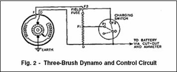
The most widely used circuit for controlling three-brush charge rates on cars built in the UK, incorporates a combined cut-out and resistance box, working in conjunction with the lighting and charging switch (see Fig. 1). In this setup, the contact position of the field brush is arranged so that it contacts the commutator “towards” the earth brush. Current travels from the dynamo output or “D” terminal (via the external control circuit) to one end of the field coils, which is brought out to the dynamo “F” terminal. After passing through the field coils the current is indirectly earthed by the field brush, at a pre-adjusted point, thus “picking up” the required fraction of Dynamo output to develop the required field current. The combined cut-out and resistance box is arranged in the charging circuit as shown in Fig. 2, and contains resistances which are inserted into the dynamo field circuit as required.
It can be seen that if the dynamo “F and “D” terminals are linked together, then
full current (for the particular position of the “third brush”) will be applied
through the field coils and a high charge from the dynamo will result. By
inserting one of the resistances in series with the field circuit, dynamo output
is reduced. Two resistances in series
with the field reduces output still further. Linking out of resistances is done
by the lighting/ charging switch, which is connected to the control box by three
wires as shown. From Fig. 2 it can be seen that low charge (“ 1/2
charge” position on switch) is in operation with all switch connections “D”, “F”
and “F2” open-circuited. Current from “D” must then pass through
both resistances before reaching the
field coils via dynamo terminal “F”. “Full charge” on the switch links out the
“D” and “ F1” terminals, which allows field current to flow through one
resistance only, increasing dynamo
charge rate. When the switch position is moved to “side lamps”, no change is
effected in the field-charging current thus remains the same. On switching to
the “headlamp” position, however, “ D” and “ F2” on the switch are automatically
linked. This by-passes both field resistances. Current flows directly from the
“D” or output dynamo terminal to the field windings. Hence an increased output
is given by the dynamo to counteract headlamp load. Maximum output is now
controlled solely by the position of the third or field brush.