Excessive handbrake lever travel on late Ruby Saloons, where the hand brake moves nearly full travel even if the brakes are in good adjustment, is usually caused by the diameter of the wheel that touches the actuating lever on the cross shaft. Remove the hand brake lever assembly, remove the wheel and replace it with five, 1” diameter plain washers with a 5/16" hole. In most cases this will remove the free play completely.
When re-fitting pistons—confused about the thrust side? Always re-fit pistons with the split skirt nearest the camshaft—sorted!
If you’ve lost oil pressure after a service and have tried all the obvious culprits – pump, drive gear, woodruff key, pressure relief valve and pressure gauge, here’s one you may not think of. There are 2 types of rear camshaft bushes! If you fit the wrong one for your crankcase, you can finish up with no oil pressure. So check the rear bush to ensure it is a good running fit on the camshaft and a close fit within the crankcase avoiding oil by-passing the bush altogether. For 3-bearing engines, check the oil feed pipe to the centre main is seated well and not fractured.
Got charging problems on the Summer circuit? Just remove the cut-out assembly; drill off the back cover, exposing two coils; either one or both will have disintegrated. Either replace with 2-ohm wire or shorten and re-fit. Problem solved!!
The first warning I had of trouble was the engine cutting out while hurtling down a hill. Then the engine cut out completely while running at full chat. Removal of the float chamber showed it to be empty. While exhibiting at the rally with the bonnet open someone must have operated the manual priming lever on the AC T-type petrol pump. The lever had stuck. This meant each stroke of the pump delivered a reduced volume of petrol. The car ran perfectly for miles and it was only when driven hard that the restricted petrol supply manifested itself. A few strokes of the priming lever making sure it was left fully down and we were away again. Examination of the pump showed the priming lever’s arms to be binding on the external spring which is meant to return it. Two bright spots on the spring showed it must have been happening for some time. Slightly widening the legs of the lever allowed it to miss the spring, the lever moving up and down freely. Many of our cars will have the T-type pump and could be at risk. I suppose the problem is most likely to be at the start of the season if the car has been standing. I understand the alternative M-type pump doesn’t have a priming lever. Essex A7C with thanks.
I have twice had starter switches (Ruby type) catch fire because dirt trapped inside them combined with oil (the starter is just below the filler cap) has caused an internal short circuit in the switch. Check yours by flicking the switch lever backwards and forwards and sideways to see if it sparks. To rectify any problems dismantle and clean.
Probably the worst disaster that can happen on your engine is to have a gudgeon pin clamp bolt work loose and come out. On its way out it will probably bend the con rod, score the bore and break the piston. It will drop on the gauze filter, be picked up by the crankshaft and smash a star-like crack in the side of the crankcase. The answer to this is not to use locking tabs but to ensure that you have new high tensile bolts fitted with spring washers and do them up really tight using ‘Loctite’ etc. on perfectly clean threads.
Jack French recommends turning the little oil jets that squirt oil down onto the troughs in the crankshaft 20deg towards the crank centre-line (Mike Forrest says 30 deg, so take your choice!) to increase the period during which the oil is squirting into the troughs. I use a piece of hollow rod which fits over the jet and bend it slowly. First clean up the ends of the jets where previous owners will have walloped them trying to remove the crank and after a gentle bending, test them by inserting a suitable piece of thin straight wire to check alignment.
Whilst travelling some 1300 miles over some terrible Irish roads recently, the only minor incident we had with the Austin was a solder fracture where the fuel pipe olive joins the pump. Not having solder and a blow lamp to hand, I cleaned the joint up, ensured it was dry and mixed up a little araldite. This was wiped over the olive and pipe covering the crack and left overnight. We are still driving about like this some 1500 miles later! To avoid cracking solder when undoing the pipe from the pump, always use two spanners, one to hold the union tight in the pump and one to loosen the pipe nut. Sod’s Law says that if you use just one spanner to loosen the pipe, the union undoes instead of the nut, twisting the pipe and breaking the solder joint!
When replacing the window felts in the runners’ channels, it is quite normal at first for the windows to bind and not slide smoothly up and down. If this happens, use French chalk or talcum powder but NEVER use any oil-based product including oil itself.
The difficulty in operating the window of an Austin Seven may be due to the moulding rail inside the door being slightly bent to put pressure on the glass. By resetting it the trouble with the window should be overcome. Also examine the channels on either side of the window in which the glass rises. These may be binding to make the action of the window stiff. If they are opened slightly and a trace of thick grease applied in the bed of each channel the stiffness should be eased. If attention to these two points fails to correct the trouble, the winding mechanism may be at fault due to rust resulting from the intrusion of moisture. Access to this mechanism necessitates removing the winding handle, which can be detached by levering the small spring catch behind the handle away from the spindle with which it engages. A loop of wire is sometimes useful for doing this. The waist-line moulding inside the door and the door catch are both held by screws which are quite easily removed, and the panel itself, which is held by screws or panel pins, can be prised away from the door. The winding mechanism can then be examined and thoroughly greased to render its action quite free. From the Austin Magazine.
If the summer ‘half charge’ switch doesn’t seem to work, look around for two resister coils—2 coils of wire about 1.5“ long and 0.5“ dia. connected together at each end. They will either be on top of the dynamo with a fuse or as part of the cut-out on the bulk head. Sometimes, a bodge has been perpetrated by connecting the two terminals on the dynamo with a piece of metal.
For cleaning the waterways you can use a mild acid as found in brick cleaner or patio cleaners found at builders merchants.
To keep your windscreen clear in frosty weather and to help your windscreen wiper in the snow, lift the offside of the bonnet and, using a wedge or piece of card between the bonnet and scuttle and close the bonnet again. You will now have a small gap which will let the hot air from the engine keep your windscreen warm!
As well as carrying a spade, candle and a box of matches (as recommended by the RAC) it is well to carry a couple of lengths of rope. You can use these as snow chains by wrapping them around your tyres and rims.
My wife keeps her legs warm in the Seven by filling a plastic bottle with hot water and placing it on the floor in front of the seat and behind her legs. We find a one gallon container stays warm for about 1½ hours.
A plastic one gallon container filled with grit can be sprinkled on snow and icy ground. A must for any motorist!
When adjusting Austin 7 cable brakes (on cars with coupled brakes) with all 4 wheels jacked off the ground, have a mate apply medium pressure to the brake pedal, or if all your mates are down the pub, wedge a block of wood between the seat and the pedal, and test the resistance on each wheel. It is most important that the brakes are tested from the footbrake rather than the handbrake, as the latter acts on the centre of the cross-shaft rather than from the offside end. The difference being the handbrake won’t pull and twist the shaft, especially if the brakes are worn, in the same way as when the pedal is used in normal road conditions. As you all know the cables should be adjusted so that the front brakes come on slightly in advance of the rear and the nearside rear should under light pedal pressure come on slightly more than the offside rear, so that under heavier pressure as the cross-shaft moves they equal themselves up. Having successfully adjusted the cables, go for a test drive and join your mates down the pub to celebrate.
This is a good time of the year to clean up your king pins. Removing the king pins once or twice a year gives you a chance to check that grease is getting down to the bottom bush and cleaning out the salt and grot from winter motoring will ensure that when the time comes to renew your pins and bushes, the pins are not irrevocably stuck in the front axle beam. This makes changing the king pins a nice easy job instead of having to dismantle half the car and take the whole front axle to your local blacksmith.
A 12v regulator is readily available from a Morris Oxford or Austin Cambridge and the following changes have to be made: a 12v battery, all bulbs to 12v, new 12v coil and a 20-30 ohm resistor for the fuel gauge. In addition, I have found that Cibie lamp units from a Renault 4 give excellent lighting whilst looking better than the reverse taper rims needed to fit Lucas 700 units.
Forming your own centrifugal weight springs can be achieved from a readily available open 3/16” spring. Slide it on to a 3/32” drill or similar (nail?), gently heat with a blow torch until a dull red, squeeze up the spring until closed and sparingly spray with water to cool i.e. - not too quickly. Cut to a suitable length, make off the ends and fit. It does take a bit of patience, but it works!
In an A7 Chummy, install an additional bulkhead forward of the fuel tank to affix any extraneous new fittings such turn-indicator units, additional fuses etc. (I find screwing these directly to the existing bulkhead severely worsened my fuel consumption and gives rise to an awful petrol smell!) Make the new bulkhead of good quality ply. However, the base of the contact breaker unit needs to be earthed as wood isn’t the best electrical conductor.
If you’ve tried undoing the nut on the pinion inside the torque tube to remove the bearings, you will know how difficult it can be. Not only have you to remember that the nut is usually a left hand thread but usually it will not budge no matter how much effort you apply to the spanner. To overcome this problem place the pinion in a wide vice as close to the nut a possible and tighten as much as you can. Heat the nut quickly and as much as you can without heating the pinion unduly. Then quickly apply a chisel to the corner of the nut and give it a hard hit with the hammer. “One hard hit is worth a thousand soft ones”.
When removing A7 low compression, 18mm, cylinder heads, to save hammering a screwdriver or chisel between the joint, try using the hook end of a Ruby boot key into the plug holes of numbers 1 and 4 alternately. Even better, get 2 boot keys and make it even easier. This dodge does not work for 14mm heads.
When you have put a new spring in your drag link it is always difficult to compress the retaining cup to get in the 1/4 BSF bolt to hold it all together. I use an old screwdriver which is about 3/16 diameter with its tip ground to a conical point. This can then be used to enter the bottom of the bolt hole and then levered across to locate the bolt entering from the top. Make sure the bolt has a radius-ed end so that it enters each part of the assembly easily - having said that you will still need to give it a gentle tap to overcome the spring once it is far enough engaged and you remove the screwdriver.
You know the problem: a saw-cut needs to be made or a hole drilled in a particular place where the light is not good and the metal is inevitably blackish or black-painted. Identify the general area for the cut or hole, place a piece of ordinary masking tape on it, mark the line or spot with a black ball-point or dark pencil, do the job, and pull off the tape – hey presto, job done and no unsightly marks left on your little beauty!
In replacing the sump, I’d fitted new set screws – those nice long-headed ones with the oval washers. What I had forgotten, was that for the centre rear one, you have to use a short one – otherwise, yes you’ve got it, the tip just catches on the starter ring……
Before undoing the timing gears, remove the fuel pump entirely from the crankcase and don’t replace it until after the new gears have been firmly installed. If you don’t do this, the camshaft may move backwards once the timing gears have been removed allowing the petrol pump cam-follower (lever-thing) to slip to one side of the pump-drive cam and jam things up! Even after re-fitting the pump it will be judicious to check things are where they ought to be by gently turning the crank by hand. If the cam follower has been displaced, a firm ‘clunk’ can be felt as the crank hits the obstruction.
If you’ve tried undoing the nut on the pinion inside the torque tube to remove the bearings, you will know how difficult it can be. Remembering that the nut is usually a left hand thread, place the pinion in a wide vice as close to the nut as possible and tighten as much as you can. Heat the nut quickly and as much as you can without heating the pinion unduly. Then quickly apply a chisel to the corner of the nut and give it a hard hit with the hammer. “One hard hit is worth a thousand soft ones”. And hey presto, you’ll almost certainly find the nut has moved.
To release the large aluminium pulley at the end of the camshaft, hit it sharply sideways against the edge of one of the holes so as to try to rotate the pulley on its shaft rather than trying to hit it from behind along the length of its shaft.
Morris Minor brake cylinder adjusters can be reversed so that the screwdriver slot faces the back plate. Drilling the appropriate hole would allow adjustment from the rear. The hole needs to be 3/8" as the adjuster changes position as it is adjusted and you also need to cover the hole as well to keep water out. All this means that by drilling a couple of carefully aligned holes in the back plate it saves all that hassle of drilling the cast iron brake drums and removing the wheels every time you want to adjust your brakes.
If new brake cams have a sharp edge where they push against the brake shoe, it must be rounded off. Also, look for a groove that may have been worn in the old brake shoe by previous cams. Should your brakes lock-on, it may be that the cam has lodged underneath the groove. In which case, drive the car in the opposite direction and it should release. In a worst case, a plate can be attached to the end of the brake shoe to remove the groove.
When using an RCD safety adapter, which you should always use with power tools, it is most important that you plug it as close to the tool as possible. I.e. if you are using a 100 foot extension lead, put the protector at the power tool plug, not at the mains supply at the start of the extension lead. The reason being that if you put it too far from the tool, electrically speaking, the delay due to the resistance and voltage drop down the extension cable, may well prevent a vital trip out in the event of an accident. Another tip, if using an extension cable reel, you must fully unwind it from the drum, before use, otherwise the coiled up cable will act as a resistor and cause voltage drop, and will result in the cable heating up and at worst catching fire.
As the input shaft bearing of an Austin 7 3-speed gearbox wears, the oil returning quick thread gets damaged in the nose piece, allowing oil to leak onto the clutch. A simple and cheap way to overcome this problem is, firstly, to renew the bearing and then insert a modern oil seal in the nose piece between the input bearing housing and the roller bearing. This stops oil from reaching the worn quick thread. There are 2 types of seal: either Payen NA080 or Payen NA092 will do the job and they are simply a press fit in the housing, It is a good idea to grease the new bearing as hopefully no oil should now reach it.
I had just completed rebuilding a Chummy some years ago and went on a maiden voyage to club night. I filled the tank and set off. Immediately after braking for a roundabout, the engine compartment burst into flames. Luckily, a passing motorist phoned the Fire Brigade and it was put out, but not before destroying the loom and taking the paint off the bonnet and scuttle. Observations: Do not over-fill the tank, ensure you have a good fuel tight seal on the cap with a screw cap, not the bayonet type, similar to the oil filler which presents more of a challenge. Also fit plastic HT plug tops and discarded the bare brass type which are asking to cause a fire if fuel is splashed on them, non original I know, but ...... Finally ALWAYS carry a good and functioning fire extinguisher with you.
To get the right flow of electricity to plugs, make sure the following connections to the coil are the correct way round:
Negative Earth cars: the negative tab on the coil (-) goes to the distributor/contact breaker. The positive tab (+) goes to the battery (+) via the ignition switch.
Positive Earth cars: the positive tab on the coil (+) goes to the distributor/contact breaker. The negative tab (-) goes to the battery (-) via the ignition switch.
On older coils with SW and CB marks, rather than + or -, one cannot tell what car they were originally designed for and so the following flow test can be performed with a sharp, soft pencil (if you are brave enough and not fitted with a pace-maker!): With the engine running, disconnect a plug lead from the top its plug and hold the end of the lead about 1 cm away from the top of the plug so that it makes as long a spark across the gap as possible. Introduce the tip of the pencil into the electrical stream. The ‘lead’ of the pencil will be seen disintegrating and blowing away in the direction of the electrical stream which should be towards the plug top. However, it is probably safer to go out and buy a modern coil!
It is often difficult to remove rust from small, intricate parts but the following electrical process works well: Ingredients:- plastic container, a piece of lead, a handful of salt or bicarbonate of soda and a direct current source of electricity. This can be provided directly from a car battery or through a battery charger. Thoroughly dissolve the salt or bicarb in a quantity of water. The rusty article is attached to the negative terminal, the piece of lead to the positive terminal and both are then immersed in the solution making sure that the two metals do not touch one another. Turn on the power supply and watch the bubbles rise. These bubbles are hydrogen and oxygen and both are highly explosive. Do not carry out this operation in an enclosed space! The hydrogen takes oxygen from the rust leaving a loose sludge that can be washed away, probably needing a wire brush, before applying a primer. The time taken depends on the area and thickness of the rust and the amperage used with heavy encrustments taking several hours. After a time, the lead will become coated with a sludge which, if left, becomes a hard deposit and so should be cleaned from time to time. The article is unaffected but, if left in the salt solution for too long would soon be attacked. The solution becomes rusty and muddied but, as long as bubbles appear, the process will continue to work. With many thanks to Phil Allman from the Isle of Wight Austins Club.
1931 SWB BOX SALOON: REAR NEARSIDE WHEEL BROKEN SPOKES. Having replaced two broken spokes last July, I have now discovered two more on the same wheel and the same inside, short spokes as before. Is this just bad luck or is there some underlying problem to do with suspension or back axle? Bob Plummer
-
Our expert writes: I doubt whether it’s a problem with suspension etc. as Austin centre wheels (which it should have) are notorious for breaking spokes. I stopped fitting Austin centre wheels to my 1930 Box years ago and fitted the later, chrome centre ones which are much stronger. When replacing spokes, an expert should re-tension them all and re-true the wheel. Ian Dunford, Vintage Austin Services, does rebuilds (see grey mag advert) and, more locally, James Wheildon at Brickwood Farm West Grimstead Salisbury 01722 712701 e-mail: jameswheildon@yahoo.com. Shot blasted and stove enamelled wheels seem to be more prone to this—it may be the blasting weakens them and the stove enamelling heats and loosens them. Septimus
Engine oil diluted with paraffin is perfectly suitable for the lubrication of leaf-type road springs and it is widely used for this purpose. The springs should be thoroughly cleaned by scraping and brushing, then the car should be jacked under the chassis so that the springs are opened as much as possible. The diluted oil can then be sprayed or brushed on. The mixture is just as good as penetrating oil and considerably cheaper. No particular degree of dilution is recommended but a half-and-half mixture will serve admirably.
If you have a fuel supply problem check the fuel-feed needle valve assembly from the underside of the fuel chamber lid, it might have a speck of debris trapped in it giving an intermittent feed.
A small flat rotary wire brush that just fits inside the distributor cap will clean all four contacts and the carbon brush in a trice.
If you suspect you may have an induction leak around the carb or manifold, spray on some carb or brake cleaner from a can whilst the engine is running and, if the engine is sucking in air, there will be an immediate and noticeable increase in engine revs. Colin Chalk
On the coil there are terminals usually marked CB and SW in Lucas sets. These are connected to the contact breaker and to the switch respectively. Even if they are not marked in this way they can be recognized by their obviously low-tension cables. The lamp bulb can be connected in two ways. One is to insert it in series with the coil. For that purpose the cable from either of these two terminals must be disconnected and attached to one terminal of a lamp holder or adaptor, obtainable at any electricians or at some of the sixpenny stores. The other terminal of the adaptor must be connected to the empty terminal of the coil. In this method there may be only a feeble glow from the lamp because its resistance is added to that of the coil and therefore only a small current will flow. However, the light will usually be quite discernible and so soon as it disappears one knows that the contacts have separated. By an alternative method it is possible to obtain the same result, but with a brighter light and without undoing a single terminal. In this case the bulb is placed in parallel with the coil. That is to say, the terminals of the lamp holder are connected to the two terminals on the coil. All that one needs for that purpose are two short pieces of stiff wire, attached one to each lamp terminal so that they can be "touched" on to the two coil terminals while the engine is cranked gently round. To get the exact point of ''break" the final movement of the crankshaft can be made very conveniently by turning the fan pulley backwards or forwards.
A suitable bulb for use in this case as in the other can be taken from a sidelamp of the car. There is thus remarkably little expense in rigging up this useful apparatus. For those who may indulge frequently in ignition-timing experiments, it is well worth having, and another even cheaper device to go with it is a mark on the lower fan-belt pulley to show when No. 1 piston is at top dead centre. Frequently there is such a mark on the flywheel, but it will avoid repeated removals of floorboards and/or clutch-pit cover if a T.D.C. indicator is made at the other end of the crankshaft, where it can be seen without removing anything. Light Car Jan 1940.
One of the most unreliable aspects of the 3 speed gearbox cars is the slotted collar clutch thrust bearing. The clutch levers have a nasty habit of wearing through the collar at the most awkward of moments, necessitating removal of the engine to restore the mess. Instead of re-cutting 3 new slots, a far more reliable alternative is to fit a 4 speed gearbox type clutch thrust, which simply slides on in its place. When the gearbox is bolted up to the engine, make sure there is clearance between the race and the levers and that when the pedal is depressed the clutch disengages fully. If not, bend the 3 levers with a long pipe accordingly. Once bent make sure all 3 are exactly the same distance from the centre plate to avoid premature wear and judder.
The pedal rod end spring can now be dispensed with as there is no need to keep the race in constant contact with the levers as there was before. Mouse trap springs need not be fitted, nor the 4 speed box race return spring but, if preferred, the later wide foot clutch levers may be used. The above simple and unseen modification should result in a more reliable set up and a smoother clutch operation. Mine has been fitted for about 40,000 miles, so far without any problems.
(PS: 2007, still fitted! If you use late levers you will have to heat them cherry red before bending as I believe they are cast. Of course there are other methods of adjusting the levers if you so wish, on this there are several articles. Munwellyns and now GM Autoservices always heat and bend all. Some people prefer to fit mouse trap springs, (not easy), but Glyn and I have never found it necessary.) Gary Munn
If you need to take off your dynamo to change the brushes and do not want the hassle of re-timing afterwards then this can be achieved quite simply. Put the car in neutral and remove the distributor cap and rotor arm. Turn the engine over with the starting handle until the notch on the central spindle of the distributor (that the rotor arm locates on) aligns with the foot of the contact breaker. From this point onwards ensure the engine is not turned or moved. Remove the dynamo and replace the brushes. When refitting make sure that the notch and contact breaker foot once more realign. If not slide off the dynamo and turn it slightly before refitting and repeat until alignment occurs. This is easier that it might sound because one tooth rotation on the dynamo means a significant misalignment at the notch/contact breaker. Don’t forget to replace the rotor arm! Peter Trebilco
One way to prevent oil spilling (or dripping) onto the ignition wires and the starter motor etc., is to temporally extend the oil filler tube. I use a plastic Coke bottle with the bottom removed, the screwed top seems to just fit nicely into the top of the filler tube of my Box saloon and the ignition wires support the bottle too. Now I rarely spill any oil over the off side engine area. Sandy Croall (Cornwall A7C) with many thanks.
If your door key, or any other key for that matter, is a bit 'sticky' in the lock, don't use oil to free it off, rub the key with a soft lead pencil. Most pencil leads are made from graphite, which is a great lubricant, with the added bonus that it will not attract dust and dirt like sticky oil will. You can also buy powdered graphite which can be 'puffed' into keyholes. You can also rub the pencil over the latch on your door, this will make it shut a lot easier. Lee Webster. Cornwall A7C with many thanks.
To check the polarity of an A7 - Most Austin Sevens were originally negative earth but I have come across some that aren’t—perhaps they were changed over in the 60s when many ‘modern’ cars became positive earth to help prevent rusting (it was thought). To save doing any damage to your dynamo, or reversing its polarity by mistake, replace the battery with the normal negative going to earth, i.e. the body of the car, do not start the engine but switch on the headlights and look to see if the ammeter is showing a discharge. If it is showing a charge, then the cables are the wrong way round. However, the terminal posts on most batteries should be different sizes as should the connectors so you should also be able to tell when you try to refit the terminals to the battery.
The "spit and hope" type lubrication of the Seven makes it most important to keep a watchful eye on your oil pressure gauge. You will soon see that when the engine is cold it swings off the scale but, as the oil gets hot and thins, the pressure drops back to less than 5 lbs under normal driving conditions. This is quite normal. However, when hot, should it uncharacteristically rise dramatically, immediate measures need to be taken. One of the most important items to carry at all times is a length of 1/16th rod or stiff wire about 6-8 inches long. A sudden rise in oil pressure usually means that there is a blockage in one of the oil jets supplying the big ends and, if left unattended, this would cause starvation and big-end failure. These jets are covered by 2 small brass bolts on the offside of the engine crankcase either side of the oil filler tube. To clear a blockage, turn the crankshaft 1/4 turn on the starting handle, undo the bolts and carefully poke the wire down through each of the jets—it should go down about 3 inches plus, (it may take a few attempts to get the feel of it and locate the holes, why not have a dry run at home as practice?) This will ensure each jet is free of obstruction. Replace the bolts and start her up and check the gauge. Hopefully this will avoid an expensive engine rebuild!! Gary Munn
1. Check the brake shoe pull-off springs. Replace elongated or miss-shaped springs with new.
2. When you have to reconnect the last brake shoe spring, loop a length of string through the spring hook, pull it tight and tie-off on something. Now push the spring in position around the hook on the brake shoe with a screwdriver. Release string. Remove string. Job done!
3. It is most important that the brake linings are not impregnated with grease, etc. Stick masking tape on the linings to protect them until the dirty work is done then just peel it off.
4. When you have replaced the brake linings you probably will not be able to get the brake drum on again. Remove any adjuster you have on the cable. If the drum still will not go on, slacken off the foot pedal adjusting screw. This allows the brake cross-shaft to turn back and allows the brake shoes to fully return to normal. Now the drum should go on. If not, bad luck! It means you have to slacken the clamp bolt in the brake cable forked end and pull the cable out a bit. Terrible job! Don't pull it right out as it is a so and so of a job to get it back into the forked end again!
With thanks to Viv Orchard from the IOW A7 Club
Austin
Sevens have always been prone to catching fire. The main cause is the
lethal mixture of oil and sparks which can occur together around the
starter 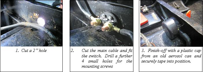 motor
terminal. Oil can drip from the filler tube directly down onto the
electrical terminal below and, should the securing nut become loose and
a spark develop or the insulation becomes oil-soaked, the hot oil
quickly ignites. On a less dramatic point, I have always been happier
when putting Baby to bed, to know that everything electrical is
disconnected and there is no danger of a nightmare developing unseen.
The answer: to fit an isolator master switch
in the main power lead from the battery. There are two sorts – a simple
turn-key affair or the more sophisticated ‘Dis-Car-Net’ battery
terminal extension, both available in all high street motor shops. For
the Box, I chose the simple turn-key as the battery is underneath the
driver’s seat and to operate the terminal switch would entail lifting
the seat and the battery cover every time. The turn-key was fitted in
the front panel of the driver’s seat mounting box and can be operated
by simply reaching down and turning the key. Later cars with the
battery under the bonnet can have the turn-key fitted through the
bulkhead in line with the driver’s right knee picking up the main
battery lead on its way down to the starter motor. The only tool I
needed that might not be in everyone’s kit was a 2” metal hole-cutter
but I saw one in In Excess the other day for £1:50! One final
advantage, of course: switching off and taking the key with you is an
excellent anti-theft device.
motor
terminal. Oil can drip from the filler tube directly down onto the
electrical terminal below and, should the securing nut become loose and
a spark develop or the insulation becomes oil-soaked, the hot oil
quickly ignites. On a less dramatic point, I have always been happier
when putting Baby to bed, to know that everything electrical is
disconnected and there is no danger of a nightmare developing unseen.
The answer: to fit an isolator master switch
in the main power lead from the battery. There are two sorts – a simple
turn-key affair or the more sophisticated ‘Dis-Car-Net’ battery
terminal extension, both available in all high street motor shops. For
the Box, I chose the simple turn-key as the battery is underneath the
driver’s seat and to operate the terminal switch would entail lifting
the seat and the battery cover every time. The turn-key was fitted in
the front panel of the driver’s seat mounting box and can be operated
by simply reaching down and turning the key. Later cars with the
battery under the bonnet can have the turn-key fitted through the
bulkhead in line with the driver’s right knee picking up the main
battery lead on its way down to the starter motor. The only tool I
needed that might not be in everyone’s kit was a 2” metal hole-cutter
but I saw one in In Excess the other day for £1:50! One final
advantage, of course: switching off and taking the key with you is an
excellent anti-theft device.
It might be wise to warn people again with starters under the bonnet to keep the switch clean and free from oil, being especially careful when topping up the engine oil as the switch is directly under the filler tube. Another good reason to install a battery master switch (See above tip) - Gary Munn
Helicoils are supplied as a kit with the correct drill, tap and insert tool - everything you need but at an eye-watering price (£73.59 including 20%
|
Bolt size |
Helicoil drill size |
Helicoil drill size |
|
3/16 |
4.9 |
5 |
|
1/4 |
6.6 |
6.7 |
|
5/16 |
8.3 |
8.4 |
|
3/8 |
9.8 |
9.8 |
|
7/16 |
11.4 |
11.4 |
|
1/2 |
12.9 |
12.9 |
|
9/16 |
14.5 |
14.5 |
|
5/8 |
16.1 |
16.5 |
|
3/4 |
19.3 |
19.7 |
discount). For this you get 10 helicoil inserts so I guess at £7.35 per repaired hole it is not too bad. With the kit (incidentally now marketed as Armstrong Precision Components - Armacoil Thread Repair Kit, Helicoil to you and me) came a table of drill sizes which I list below. To drill out prior to tapping for the Helicoil insert, very little extra metal has to be removed – really just the removal of the remnants of the old threads. This compares well with tapping out to the next size up. The special tap supplied is quite short and well tapered so care is required to keep it running straight and to avoid too much swarf build up. The helicoil inserts went in easily using the insert tool. The inserts are effectively springs and the tool slightly compresses them so they wind in easily. On release of the tool they grip tight. John Miles (DA7C)
I have had dreadful steering wander since putting the Box back on the road. I have repositioned the quadrant in the steering box, replaced both front bearings and played around with front/rear tyre pressures. But things just kept getting worse. The horrifying answer was a loose ball pin which connects the steering drop arm from the steering box to the drag link tube which goes from the drop arm to the offside front wheel steering arm. The split pin had disappeared and the ball pin was loose on its taper and on the point of coming out altogether! Answer—check the castellated nut is as hard on the taper as possible.
Do you struggle
filling your rear axle with that
thick 140 oil? Do you keep saying I must get a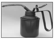 proper pump? Well, Sandy
Croall down in deepest Cornwall has passed on this oh so blindingly simple
solution. Next time you go to an autojumble or event where cheap tools are
sold, get an oil can like the one illustrated with a flexible plastic pipe
attached. They are 'as cheap as chips'. Cut off the brass nozzle, (don't try
and pump the oil with the nozzle attached it will take for ever), and hey
presto, job done. Sandy says he painted the side AXLE OIL, and found that a
tyre valve cap fits the end of the pipe to keep the oil clean.
proper pump? Well, Sandy
Croall down in deepest Cornwall has passed on this oh so blindingly simple
solution. Next time you go to an autojumble or event where cheap tools are
sold, get an oil can like the one illustrated with a flexible plastic pipe
attached. They are 'as cheap as chips'. Cut off the brass nozzle, (don't try
and pump the oil with the nozzle attached it will take for ever), and hey
presto, job done. Sandy says he painted the side AXLE OIL, and found that a
tyre valve cap fits the end of the pipe to keep the oil clean.
Austin Seven
owners, using the Zenith 26VA carburettor and suffering from poor, erratic
engine idling can now improve the situation with very little effort. If you
look at the underside of the 26VA you will notice a
brass screw head in a raised rib about 30
mm back from the manifold flange. This has always been considered in the
past as a blanking screw covering a passageway within the body of the
carburettor. This screw plug is, however, an access cover to a jet
underneath. Apparently this jet 'bleeds' a small amount of air into the
throat of the carburettor when the butterfly flap is fully closed. If you
hold up the carburettor and look into the throat from the manifold end you
will see two small holes. The furthest one of these is the entrance to the
jet which can easily become choked with dirt and leads to the rough idling.
It can be reached by taking out the blanking plug and, with a good quality
screwdriver which is able to reach far into the hole the jet, can be
unscrewed for cleaning. Do use a good screwdriver as the jet is easily
damaged You will be amazed the difference cleaning this jet will make.
Another useful tip in association with this jet is to have your car ‘gas
analysed’ on a Crypton tuner or similar. You will then be able to set the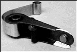 air bleed screw on top of the carburettor accurately. Note the setting by
counting the number of turns out of the air screw that gives the accurate
setting and always use this setting. Malcolm Watts Cornwall Austin
Seven Club
air bleed screw on top of the carburettor accurately. Note the setting by
counting the number of turns out of the air screw that gives the accurate
setting and always use this setting. Malcolm Watts Cornwall Austin
Seven Club
The replacement Contact Breaker sets available for the DJ4 and similar distributors have the contact hidden within a 'C' shaped lever. To set the gap at 12 thou with normal feeler gauges I have found difficult! It has also been difficult to see exactly when the contacts are opening as I check the timing. Then a clever man via Oz (Steve Jones of the PWA7C) said:-1) "Why don't you use the original Lucas contacts" or 2) "Why don't you grind away the legs by the contact on the lever". To my knowledge there are not many un-used original Lucas Contact sets about, so I decided to try the second option, but only doing the top leg, converting it from a 'C' shape to a 'L' shape, on the basis that some strength is retained with the bottom leg and I can see the contacts clearly with just the top leg removed anyway. I also painted the bottom leg under the contact white to making sighting the contacts easier - Problem solved, it's too easy for words. Sandy Croall Cornwall Austin Seven Club
Recently, the ammeter started to show that disturbing symptom of a very fluctuating charge which took some time to cut in. I did all the usual stuff - checking/cleaning the brushes, cleaning the armature and cut-out points—absolutely no difference! Then I looked more closely at the cut-out gap - it didn’t look too wide but in the usual spirit of ‘try anything’ I closed them up a tad and, lo and behold, a steady immediate full charge! But one word of warning: don’t close them so much that they don’t open - otherwise you’ll end up with a flat battery and perhaps worse! Here a battery isolating switch is a valuable safeguard! Ian Mason-Smith
We all use
circlips,
but did you know there’s a right and a wrong way to fit them? A
careful inspection of the flat sides of the circlip will reveal a dead
flat face and, on the opposite face, a slight curve on the edges.
When fitting the circlips in their groove, always have the dead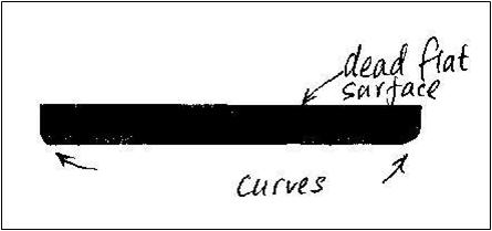 flat
face taking the force in the groove, i.e. away from the cause of the
pressure the circlip is trying to stop. Vince Leek
flat
face taking the force in the groove, i.e. away from the cause of the
pressure the circlip is trying to stop. Vince Leek
The
headlamps fitted to 1932 Austin Seven saloon cars have special
double - filament Lucas - Graves bulbs ; the main filament provides the
normal driving beam, and the secondary filament, which is slightly in
front of the main and is surrounded underneath by a shield, provides the
deflected anti-dazzle beam on operating the switch on the steering
column. On these lamps the securing screw cannot be swung clear of the
slotted plate at the base of the lamp, as is usual when releasing the
lamp front, and any attempt at forcing this screw clear will only result
in the reflector being dented from the inside. For removing these lamp
fronts, it is necessary, after slackening the screw, carefully to prise
off the front with a suitable tool and then, by swinging the top of the
lamp front forward and downward, lift the slotted plate clear of the
screw. Alternatively, the screw can be re-moved entirely, but if this is
done, it must be ensured that the anchoring plate is not pushed away
inside the lamp body, as this will necessitate dismounting the reflector
before it can be reached. The correct Lucas-Graves bulbs can be obtained
from any Austin dealer or Lucas Service Depot. From The Austi n
Magazine.
n
Magazine.
The old Box was definitely getting breathless with no power and the occasional cough or choking fit. In the true spirit found elsewhere in these columns, I tried everything until hitting on the following: The contact breaker heel was almost worn away! 1) See photo; 2) check yours; 3) change if necessary! David Whetton
Am I alone or do other A7 drivers seek a place to rest their left foot whilst not using the clutch? A little dodge I use is to undo the centre top bolt on the drivers side of the gearbox cover, drill a length of steel strip about 1.5 ins. long at one end and bolt this to the gearbox top (length is critical as it must leave clearance for your foot to depress the clutch) - Hey presto! A nice comfortable foot rest. Glyn Llewellyn
Have you inspected the rubbers on your shock absorber links lately? Being made of rubber they do tend to deteriorate over time and could be the cause of many problems such as erratic steering and poor cornering, check them out now.“Bumbling”, A7OC with many thanks.
Whilst rummaging
through a whole load of clutch levers I noticed that they aren’t all the
same! To be precise, the pivot point (marked) on some of them was much
closer to the round pin hole than
others. Clearly, the nearer the pivot is to the pin the lesser is the
movement of the lever pin, resulting in a soft pedal with a lot of travel,
and the further the pivot is from the pin, the greater is the movement of
the lever pin giving a hard pedal with a short travel.
Roger Ballard
When did you last have a peek at the relationship betwix your ‘Seven’ hubs
and shafts? Any sign of wear, marks on the key surface, sloppy fitting in
the keyway are evidence of movement however small, between the shaft and
hub, the cause more often than not being an insufficiently tightened nut. It
may also be that the hub has been riding on top of the key. To check, remove
key, fit hub and tighten nut as hard as possible with a
 socket
and a substantial lever with a suitable length of bar placed between a wheel
stud with wheel nut fitted (to prevent damage to thread) and the hub centre
extending to the ground. Carefully note position of hub nut, i.e. marking
face etc, remove nut, fit key if completely sound, and re tighten. Whatever
else you do, do not fit a sloppy fitting key. Tightening to a different
position indicates a need to file down the surface of the key until it
tightens exactly to the position achieved without the key. Unless you’re
fitting together the two components which have never previously met, proceed
with caution down the road of ‘lapping’ the hub on to the shaft with
grinding paste about which much has been written. After seven decades or
more, it surely is reasonable to assume that any lapping that’s been needed,
has already been done, who knows how many times. Over doing this lapping
lark can only eventually lead to the risk of the nut tightening against the
shoulder on the shaft beyond the threads, instead of against the hub. It is
known to have happened! For additional confidence in a secure shaft/hub
drive, the oft times repeated advice of re-checking the tightness of the hub
nuts after a couple hundred miles or so is worth considering. And at the
risk of stating the obvious, if, on the final tighten-up, you find that the
cotter pin hole is not lined up to enable fitting the cotter; resist any
temptation to slacken off to accommodate it, no matter how little. Either
fit a suitable shim washer or grind down the nut surface just enough for the
nut to be fully tightened for the cotter pin to be fitted. Incidentally, an
old wheel that has seen better days, and with the centre removed, fitted and
lowered to the ground is ideal for securing the hub while giving the nut
that final tightening heave. John McKay Scottish A7C Meshing Point
June ‘09 with
many thanks.
socket
and a substantial lever with a suitable length of bar placed between a wheel
stud with wheel nut fitted (to prevent damage to thread) and the hub centre
extending to the ground. Carefully note position of hub nut, i.e. marking
face etc, remove nut, fit key if completely sound, and re tighten. Whatever
else you do, do not fit a sloppy fitting key. Tightening to a different
position indicates a need to file down the surface of the key until it
tightens exactly to the position achieved without the key. Unless you’re
fitting together the two components which have never previously met, proceed
with caution down the road of ‘lapping’ the hub on to the shaft with
grinding paste about which much has been written. After seven decades or
more, it surely is reasonable to assume that any lapping that’s been needed,
has already been done, who knows how many times. Over doing this lapping
lark can only eventually lead to the risk of the nut tightening against the
shoulder on the shaft beyond the threads, instead of against the hub. It is
known to have happened! For additional confidence in a secure shaft/hub
drive, the oft times repeated advice of re-checking the tightness of the hub
nuts after a couple hundred miles or so is worth considering. And at the
risk of stating the obvious, if, on the final tighten-up, you find that the
cotter pin hole is not lined up to enable fitting the cotter; resist any
temptation to slacken off to accommodate it, no matter how little. Either
fit a suitable shim washer or grind down the nut surface just enough for the
nut to be fully tightened for the cotter pin to be fitted. Incidentally, an
old wheel that has seen better days, and with the centre removed, fitted and
lowered to the ground is ideal for securing the hub while giving the nut
that final tightening heave. John McKay Scottish A7C Meshing Point
June ‘09 with
many thanks.
I recently converted both my Austin 7s to contactless, or electronic ignition. Both my Austins are 12 volt with Boch distributors as supplied by Willie MacKenzie, however I am given to understand that a 6 volt version is available. It is very easy to fit, just remove the points and condenser from your Boch distributor and screw in the base plate of the ignitor in its place, push the circular magnet sleeve onto the distributor shaft, making sure it goes right down to the lip (it's a tight fit) refit the rotor. Connect to red wire to the positive side of the coil and the black wire to the negative side of the coil (negative earth) Job done. I do feel however that the 'Ignitor' and the appropriate Flamethrower coil should be bought together. The manufacturer is Pertronix look at www.pertronix.com. The total cost of the Ignitor and the Flamethrower Coil was about £120 . Definitely gives improved performance and smoother running. I purchased it through Coolair.com Glyn Llewellyn
Now that Spring has Sprung it is time to do those routine under-chassis greasing jobs. Pump sufficient grease in to clear away any old grease particularly in suspension joints and kingpins where road dirt will combine with grease to form a very effective abrasive inside sleeve type bearings. Spray leaf springs with motorcycle chain lubricant. Bumbling, A7OC Magazine
How about this tip from "Workshop Wrinkles and Recipes" edited by Percival Marshall in 1935. Repairing filament lamps - shake the bulb whilst the current is on - the broken ends of the filament will touch and weld together. This has got to be the ultimate in money saving tips for the Seven owner. Bumbling, A7OC Magazine (A7OC)
A little trick for cleaning up metal filings or swarf: Wrap a magnet up in some rag and pick up all the metal into the cloth, then removed the magnet—nice and clean! Gary & Colin
Poor insulation on your plug leads: It is normal for this insulation to deteriorate over time as it was originally made of rubber, which is a natural biodegradable material; this is why you occasionally get an electric shock when touching the leads when the engine is running. To check, run the engine in total darkness with the bonnet open and look for a blue hue on the outside of the plug leads – this shows that some of the electricity is taking the easier path to earth down the outside of the lead rather than having to jump the 25 thou gap from the central conductor of the sparking plug to the earth prong. Modern cable is made with neoprene sheathing which does not deteriorate. However, it does come with two kinds of central conductor. Ensure that you buy the version with a real copper centre conductor otherwise you will have trouble fitting the original terminals on either end. The other type has a graphite based core to automatically provide ignition suppression for car wireless reception. Yours Bumbling (A7OC) With many thanks
To help with setting the clutch cross shaft in its foot-pedal pinch bolt, something better than a slot in the nearside end is needed. Next time the gearbox is out of the car, take out the shaft if necessary and drill and tap the end 5/16” BSF and glue in a high tensile bolt with Loctite Studlock. You can then use a spanner to hold the shaft in a forward position when doing up the pinch bolt. At the same time the opportunity should be taken to fit a Ruby type clutch pedal arm and detachable pedal. Having detached the short stub of pedal, the pedal arm can be more easily removed, allowing the engine to be taken out and refitted without the usual interference from the floor-plate. Ron Hayhurst BA7C with many thanks
We have received a communication from Messrs. Joseph Lucas, Ltd., to the effect that, in the case of cars fitted with Lucas Dip and Switch Headlights, the lights should never be switched off while the reflector is in the "dip" position. This is because, as described in the last issue of the journal, the reflector is held in the dipped position by means of a solenoid. When the current is switched off, the solenoid ceases to function, and the reflector springs back into the normal position. When the lights are again switched on, the solenoid comes into action immediately and dips the reflector. The filaments in the bulbs, when either cooling off, or getting warm, are exceedingly brittle, and the jar caused by the dipping or releasing of the reflector, when the bulbs are in this condition, has a great tendency to shatter the filament and render the bulb useless. Austin Service Journal July1930
Emergency replacement dynamo brush-spring. Now those of you who have tried spring-replacement will confirm that that this is not the most jolly job, especially whilst enjoying an A7 holiday – even with the support of Andrew Jarmin’s expert and generous workshop facilities. As recommended, I always have the dynamo brush-cover off to assist the cooling of vital parts – so no obstacle there. Take a good chunk of ordinary car-washing sponge – yes those big yellow jobs – just tear off a sizeable bit and jam it firmly between the dynamo casing and the brush-holder. Hey presto! a brand new brush-spring (probably cleans the commutator as well). Result – a great charge of 10amps, good enough even to hold the Chummy headlights! Ian Mason-Smith
Whilst removing your battery for winter storage it is a good time to inspect the battery box for any signs of corrosion, clean off any rust and treat with special acid resistant paint available from good motoring accessory shops. When reinstalling the battery after the winter ensure that you treat the battery terminals with petroleum jelly (Vaseline) to prevent future corrosion. Incidentally the corrosion (blue stuff) which may be present on your cable terminations can be removed very effectively by removing them from the cable and then running them under hot water. Bumbling (A7OC with many thanks)
How to remove a stubborn woodscrew, the slot for the screwdriver having been damaged? First centre-punch the centre of the slot and using a 1/16th drill and drill the screw until you have reached the bottom of the screw head. Successively increase the size of the drill drilling to the same depth until you reach the full size of the screw head. This will allow you to remove the item attached by the screw and leave a small stump which you can grip with a Molegrip with sharp teeth. Lock the Molegrip on and rotate the stump backwards and forwards carefully until you break the seal between it and the wood. The remainder of the screw should come out easily now - ‘Bumbling’ (A7OC) with many thanks.
Should you be building a 2-bearing engine from spare parts, make sure you have the correct camshaft bushes fitted at the front and back of the crankcase as there are two different sizes: the earlier crankcases (with the starter inside the car) have a smaller outside diameter for both front and rear bushes than later engines (with the starter under the bonnet) and the front bush is also slightly shorter. It is important not to confuse these with the ones fitted to the later crankcases as they look the same to the naked eye. Should the earlier ones be fitted in a later crankcase by mistake, there would be no oil pressure as the oil would simply flow down the sides of the bush. The inside diameters are the same on both crankcases. If in doubt, the bushes should be a snug fit in the crankcase in both instances usually requiring a light tap. Also check that you have the bushes the right way round as the oil holes must align with the holes in the crankcase. Another useful tip is to replace the square peg bolt that secures the front bush with a 3/16 inch Whitworth bolt of exactly the same length, and then tap a 3/16 inch Whitworth thread into the larger peg hole in the bush. This allows the bush to be bolted up tight after assembly. Bolt the rear bush into the crankcase first, making sure that you line up the oil holes, fit the front bush on to the camshaft then “glue” the 9 centre rollers into their slot in the shaft with grease and lower the assembly through the front of the crankcase taking care not to dislodge the rollers, carefully lining up the front bush as you lower it in so that the bolt holes line up. If you are lucky, the rollers will slide into their cage first time but it could take several attempts! Screw the new bolt and a fibre washer into the front bush - job done, simple. If you are building the later 2 bearing engine, you will need the camshaft with the extra cam to drive the mechanical petrol pump. The 3-bearing engine is different again, but that’s another story. Glyn Llewellyn
"Q:
I
have
an
Austin
'Seven'
Tourer,
and I
am
having
trouble
with
whining
or
somewhat
high
pitched
moan
that
appears
when
the
foot
is
lifted
from
the
accelerator.
It
appears
only
when
the
foot
is
lifted,
with
very
slight
depression
of
the
accelerator
the
noise
disappears.
Lately
it
has
been
getting
worse,
and
a vibration
now
accompanies
it. I
have
had
various
suggestions
given
me
as
to
the
cause,
one
being
slackness
in
the
final
drive
between
the
bevel
and
the
crown
wheel,
but
this
is
hardly
borne
out
by
the
fact
that
the
whole
of
this
was
new
two
years
ago.
Also
the
noise
is
noticeable
only
in
top
gear.
It
may
be
present
in
second
and
bottom
and
the
noise
of
the
gears
drowns
it,
but I
have
listened
carefully
and
have
not
noticed
it
in
those
two
lower
gears". L.F.G.
(Wallingt on) A:
The
trouble
lies
in
the
clutch
thrust
race
which
is
worn.
Also
there
may
be a
little
end
play
on
the
crankshaft
which
adds
to
the
noise
in
the
thrust
race.
De-pressing
the
clutch
pedal
will
alter
the
noise.
If
the
whine
is
heard
on
the
road,
it
may
be
in
the
rear
axle
and
the
bevel-pinion
shaft
should
be
removed
and
the
ball
race
examined
for
wear.
Adjustment
will
only
make
matters
worse.
Jack
up
the
car
over
a pit
and
listen
for
location
from
underneath.
From The
Practical
Motorist
1935
on) A:
The
trouble
lies
in
the
clutch
thrust
race
which
is
worn.
Also
there
may
be a
little
end
play
on
the
crankshaft
which
adds
to
the
noise
in
the
thrust
race.
De-pressing
the
clutch
pedal
will
alter
the
noise.
If
the
whine
is
heard
on
the
road,
it
may
be
in
the
rear
axle
and
the
bevel-pinion
shaft
should
be
removed
and
the
ball
race
examined
for
wear.
Adjustment
will
only
make
matters
worse.
Jack
up
the
car
over
a pit
and
listen
for
location
from
underneath.
From The
Practical
Motorist
1935
Another use for a worn out brake drum: Drill 2 x/8 inch (16mm) holes in the side of a brake drum, slip in 5/8 bar. Assembly can now be used to brace the rear hub when tightening the half shaft nut up tight. Roger Ballard
Battery lifter: When removing old brake linings, don’t drill out the old ones as this may damage the shoes. Instead, break of the old lining, if it will come, and hacksaw off the heads of the old rivets then punch out the remaining bits. If they don’t break off, just carefully put the saw blade between the lining and the shoe and proceed as above. Glyn Llewellyn
When replacing brake shoes, especially the fronts, take off the hubs first to remove and replace shoes. It saves a lot of sore fingers, a lot of time in the end, and gives you a chance to check and grease the bearings. Ian Mason-Smith
Battery Handle Mk.2 As a follow-up to the recent article dealing with the same subject of getting the 6v battery out of its hole in the floor (see diagram opposite), hopefully the pictures are self explanatory with the simple ingredients being a length of plastic water pipe, two plastic number plate screws with nuts and finally, two spare battery caps. Obviously dimensions to suit individual batteries. Gordon Cowie
Did you know that the original Lucas headlights on a Ruby have a second inner metal silvered ring around the inside of the glass lens which the “w” shaped springs bear on to hold the glass in place? This has got a cork gasket between it and the glass which forms a seal to protect the silvering on the reflector from water. Some people have been known to assemble the lights with these items missing. “Bumbling” A7OC with many thanks.
So how does one remove that thin
-walled oil filler tube without collapsing it and rendering it useless? I managed to find a piece of heavy gauge pipe which just fitted inside and after making sure nothing nasty could drop into the engine and with pipe in place I was able to unscrew the tube with an oil filter remover without crushing the tube. Richard Bishop
Following Roger’s excellent article on repairing threads, I
thought it wise to offer a timely reminder about the dreaded
side water manifold fixings following
a disaster I had in my very early days of Sevening! When drilling and
tapping the fixing bar for the side water manifold in the block, you need to
be very careful only to drill and tap the bar itself as the central cylinder
bores are immediately behind it and, if not careful, you will pass through
straight into the barrel itself rendering the block only repairable with a
new cylinder sleeve! The same care needs to be taken, of course, when
screwing in your fixing stud or bolt. If the bolt is too long,
 the same will
occur! Beware.
Gary Munn
the same will
occur! Beware.
Gary Munn
Cornwall Club member Steve Baldwin has attached an LED high-level stop light to the rear end of his Box. It is screwed firmly through the spare wheel cover and wired-in to the normal stop lights below. However, there is one proviso—they will only work for 12 volt conversions, of course. They can be bought from SVC for £25 Contact Tel: 01827-67714 or ordered on-line at www.s-v-c.co.uk/product/small-led-high-level-brake/. Steve Baldwin CA7C
Geoff Hardman (CA7C) had a fuel-line blockage which he effected a temporary repair by blowing back down the line with a foot pump fitted with a beach ball inflator as a makeshift airline. However, after a repeat blockage amore serious attempt was made. This time, he dropped the bung and removed the first curly section of fuel pipe just in front of the tank. After considerable prodding and shovingan inch-long plug of what looked like varnish shot out of the tank uptake pipe. Then a piece of Bowden cable was threaded through the offending pipe. and spun using a hand brace (too much petrol around to use the cordless drill!) in an ANTICLOCKWISE direction. It unwinds inside the pipe, spreads out and buffs the sidewalls a treat. A final puff with the airline and we’re done. Geoff Hardman CA7C
To
The amount of charge a battery requires is naturally determined a by the calls on its current. To verify if your battery is being overcharged remove each cell cap while the engine is running at a speed sufficient for the dynamo to operate, and then observe if the electrolyte is in a state of slight effervescence and giving off bubbles of gas. Use an electric torch if a light is necessary for this examination, as the gas might ignite or explode if a naked light is used. As the density of the electrolyte varies directly with the state of charge, the condition of the battery can be more positively determined with the aid of a hydrometer, an instrument for measuring the specific gravity of the electrolyte, which can be purchased for a few shillings from any garage. The specific gravity of the electrolyte when the battery is fully charged should be about 1.28 to 1.300 as indicated by the immersion of the hydrometer float in the electrolyte, drawn into the hydrometer. When fully discharged the hydrometer will indicate a specific gravity of about 1.115. It should be remembered, however, that these readings are subject to the electrolyte mixture being correct. If the level. of the electrolyte has not been topped up to. its proper level with distilled water (i.e. up to. the tops of the separators) its specific gravity will be high, giving, an optimistic indication of the state of-charge. On the other hand, if at any time the acid has been spilled and replaced with distilled water, the electrolyte will, be weak, and a correspondingly low specific gravity reading will be given. When gassing through over-charging takes place, topping up will be more frequently required, and acid fumes may pass out of the vents and attack surrounding objects. Usually these are not serious effects and overcharging is not so harmful as the effects of persistent lack of charge, but you should be able to judge to what extent the "Full Charge" switch position should be employed to keep the battery in good condition without undue over-charging.
Over the last two years I have had three incidents which left me stuck at the side of the road because of flaked tank coatings blocking the fuel pipe inlet at the petrol tank. Short of removing the tank it is a difficult problem to deal with. Our Box Saloon had a tank coating done by me around 30 years ago. It has caused me to be stuck twice due to on-going flaking of the coating. I have flushed it out twice and have found a small suitable filter to slip over the inlet to avoid pipe blockages. This is cheap and easy to fit and will suffice to keep you rolling. I recommend that when the fuel level gets to around a gallon the tank is drained into a bowl a couple of times a year just to avoid any major build up. The filter cannot close off the inlet to the pipe as the pipe is held in place by a metal stay. This in turn prevents the filter from closing off the inlet. The area of the surface exposed to the fuel filter area is greater than the inlet area of the fuel pipe. The protruding filter sits comfortably into the recess in the tank drain plug. George Mooney DA7C
When was the last time you checked the oil level in your back axle? Regular checks ensure that the bearings and gears will not fail you. Remember to use D140 grade oil; do not use EP140 as it has a detrimental effect on some of the components within. Whilst you are under the car make sure that you have greased the universal joints (both ends on later cars). Excessive backlash (rotation of the propshaft without rotation of the half
-shafts, and front to back movement of the pinion) is indicative of worn pinion bearings. Too much movement will lead to catastrophic failure of the teeth on the crownwheel and pinion. Check it now – especially if your back axle is noisy, best to replace the bearings, both new and second-hand crown wheels and pinions are very expensive. “Bumbling” (A7OC) with many thanksAUTOBUMBLERS
OCCASIONAL TIP OF THE MONTH No. 93 (A7OC) tells us
“The main reason your Austin 7 stops charging is due to oil contamination of
the dynamo commutator. The oil vapour
from a worn engine mixes with the dusty residue from the carbon brushes and
slowly fills in and shorts out the gaps between the copper segments. If your
car stops charging, first of all remove the dynamo brush cover and as a
preliminary inspection check that the brushes are not worn out and that
there are no broken wires.” Being a thoroughly responsible and
knowledgeable chap he goes on to describe how to clean between the segments
whilst using the starting handle to turn the commutator. Being thoroughly
irresponsible and foolhardy, your editor has always used a more direct, and
infinitely quicker, method—sticking his finger covered in a meths-soaked rag
into the hole whilst an assistant turns the engine with the handle and
pressing the rag, and end of finger, against the turning commutator which is
obligingly turning the correct way away from your digit. The only danger is
from the spinning fan blades but, of course, this reckless quick fix cannot
be recommended by such a responsible publication as this website
David Whetton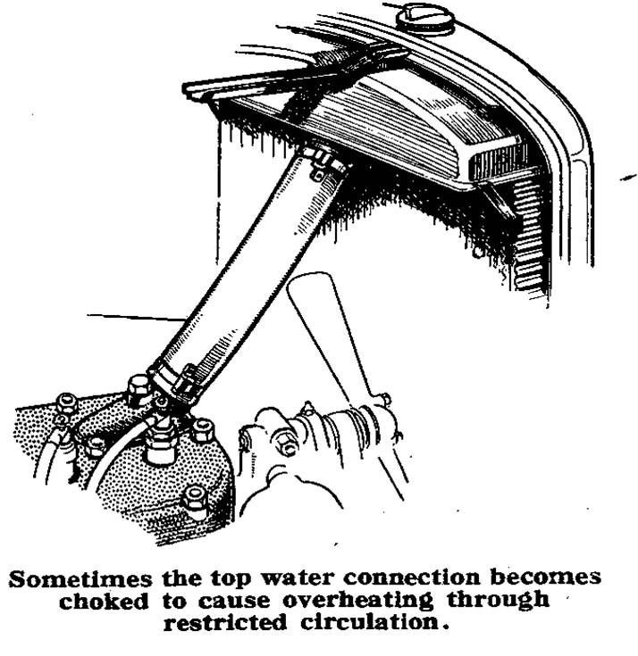
Overheating - Austin Seven. (From The Austin Magazine 1933) Q: I find that my 1928 Austin Seven seems to run hot, but there are no signs of boiling. I am wondering if you can give me your advice as to the cause. A: Overheating such as you are experiencing need not unduly alarm you unless, of course, you find that the engine boils when you get a long climb or much low gear work. Theoretically, so long as the water is not boiling, the hotter the engine runs the more efficient it is, providing that the over-heating is not due to some defect within the engine itself. Overheating arises from a number of causes. It may be that your ignition is too retarded so that the gases burn slowly and have contact with a bigger area of the cylinders than normally, thus taxing the cooling system. Again, if the mixture on which you are running is weak, there will be similar results due to slow combustion. There is also the possibility that your fan is slipping, due to the belt-tension needing adjustment, or perhaps the radiator has become choked with mud. The remedy in each of these instances is quite simple. Another possibility is a choked water connection interfering with the circulation. If you find after a run that the temperature of the top of the radiator is markedly different from that at the bottom, you should remove the top hose connection and see whether it has frayed inside to restrict the circulation, in which event a new connection should be fitted.
Horn not working? If
you
release
the
carburettor
control
leaver
tube
from
the
bottom
of
the
steering
column
you
will
be
able
to
raise
the
lever
and
unfasten
the
horn
button.
The
horn
button
is
comprised
of
two
parts,
the
portion
you
press
and
the
body
immediately
under
it.
Grip
the
lower
portion
with
a
thin
pair
of
pliers
and
it
will
unscrew,
then
you
can
pull
up
the
broken
wire
and
solder
the
original
nipple
to
it.
Or
replace
the
whole
wire
if
it
is
fractured
somew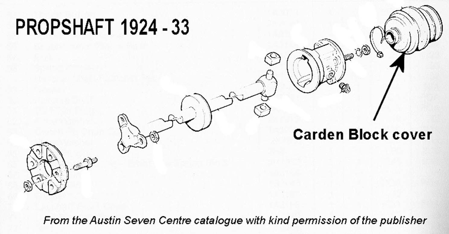 here.
Practical
Motorist
here.
Practical
Motorist
The rubber boot cover for the Carden block on the earlier propshafts from the usual suppliers is very insubstantial and has only ever lasted a few weeks for me. A much tougher option is the Mini Mark 1 cv joint boot (Delphi Lockheed part reference TBJ2197) which has lasted now for over 4 years and is available locally from the likes of Autoquip at about the same cost. Eddie Eddles Devon A7 Club with many thanks. (Also available through Mini Spares on the internet but I notice there are “inner” & “outer” boots so be careful—Ed) CARDEN BLOCK UPDATE: I have bought and fitted several Mini Rubber covers from our cherished suppliers and they are useless! They are too big on the middle diameter and rub one side of the tunnel until a hole appears and the grease comes out!! I've read your article and looked at the Mini Spares website and I see the cheap ill-fitting boots that have previously failed. Now on the same page they show a superior boot at £14.95 - is this perhaps a better fitting boot and smaller in the middle. Bryan Downes PWA7C
Rear hub nuts: Glyn and I use a 4 foot gas bar on the end of a socket bar when tightening the rear hub (taking care not to damage the hub threads with the socket). If not kept really tight, the hub works on the axle shaft key instead of the taper as it is not tight on the taper and eventually, at the very least, the key breaks but more often or not the half shaft shears off at the key. Does your Austin clonk at a back wheel area when drive is taken up between going backwards and forwards? BEWARE!!! Gary Munn
Having to tighten the flywheel on my Box, I noticed the thin tin-plate oil thrower between the rear bearing and the flywheel was just spinning loosely around and incapable of throwing oil anywhere! A quick call to Vince Leek solved the problem—the oil thrower is just pinched by the flywheel boss and will always be flattened out when the flywheel is put on. The solution is to lightly crimp the inner edge of the thrower with a pair of pliers, preferably pointed, and then fit the thrower over the sticking out end of the crank, concave face outwards, and replace the flywheel—simple! However, I did notice a scratching noise when I first turned over the engine by hand but this disappeared when I pressed in the clutch for the first time. David Whetton
Q I had an Austin 'Seven' decarbonised about two months ago. Afterwards, I found that it was pulling very well, but had a tendency for the engine to stop while negotiating left-hand corners. This tendency is gradually increasing, so that now it is almost impossible to rev. the engine in order to change up or down, or, when changed down, to pick up until the car is once more on a straight course. I do not want to readjust the carburettor, which is a standard vertical 'Zenith' unless this is necessary, as in all other cases the car pulls remarkably well and does 40-45 m.p.g. G.M.S.(Minehead)
A The controls on your car are partly seized in the steering column and counteract any pedal movement you may make on the throttle. Disconnect the arm from the bottom of the column and test this. It is the only part that can have an effect on the carburettor. From the Practical Motorist Magazine.
If you are having problems getting your core plugs to seal the following clever solution was offered to me the other day. Soak some strands of string in Hylotyte Red (replacement for Red Hermetite which is no longer available) and roll into a sausage shape. Clean the recess in the head thoroughly and allow it to dry. Line the inside edge of the recess with the wetted string where the new core plug will bear and fit the core plug in the normal manner. Tap it down with a suitable drift (suitable being about the same size as the plug) until the domed surface is flat. Leave for 24 hours before refilling or topping up engine with water. It should now be watertight. Hylotyte Red remains flexible and is easier to remove than Red Hermetite. “With many thanks to ‘Bumbling’ of the A7OC”.
A stitch in time …..
well, a drop of water, preferably distilled, to be more exact. Have you
noticed that your A7 dynamo is constantly charging your battery at about 8
amps unlike a modern car where the charge rate depends on how full of charge
the battery is? So where does all this energy go? – it boils-off the
water in your battery, that’s where. Modern batteries can be ‘sealed
for life’ because when they are fully charged, the alternator cuts off
whereas in our Babies, the charge keeps coming and the battery water gets
lower. So make it a regular job before every run to
check the battery water level
at the same time as the tyres, oil and water to save ruining the battery.
David Whetton
Distributor and lubrication:There has been much said about the Bosch Distributor and lubrication. Here you can clearly see the lube port which picks up from the gear drive end. This Distributor has been working for 14 years with no apparent wear on the drive shaft. Something must be working. People may not have noticed this lubrication channel. G Mooney
New petrol tap corks are available
from Brit-Bits in Barrack Road, Christchurch. Before fitting them do not try
and reduce the diameter even though they may appear to be too fat. First
boil them in a saucepan for 10 minutes to make them pliable then fit them on
to the spindle, smear a little Vaseline on to the cork and ease it into the
body of the tap, it may be a little stiff at first but will soon ease up
when in contact with the petrol. Glyn. Brit-Bits is open Wednesday to
Saturday 9-1pm for callers, tel 01202 483675 and has moved to the rear of
Smart Riders on 185a Barrack Road, Christchurch. The website
www.britbits.co.uk gives an idea of
the range of items stocked which can be sent by mail order.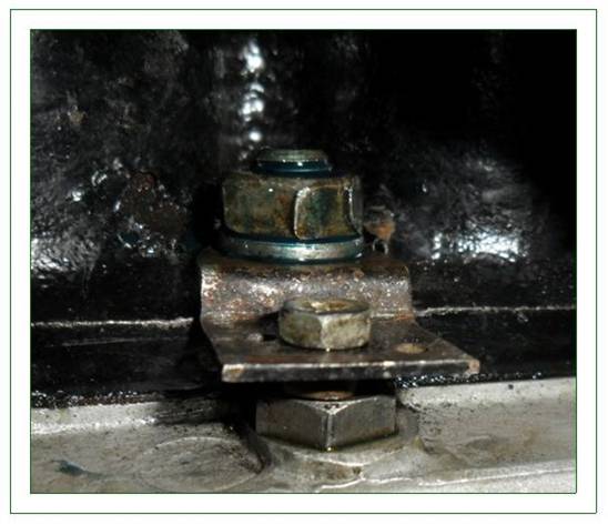
THE CASTLEMAN CLIP: When I saw a trickle of oil from one of the oil jet plugs I just thought that the plug had loosened as part of the settling-down process. But . . . you can imagine my horror when I found that the thread in the crankcase was very worn and quickly became non-existent after my attempts to tighten the plug. The prospect of dismantling the engine passed in front of my horrified eyes as this thread is (virtually) impossible to get at with the cylinder block in place, and any swarf that dropped into the oil gallery would have to be removed. So, after much head scratching, wailing and gnashing of teeth I hit upon the idea of making a small clip that fits under the adjacent cylinder block holding down nut and presses down on the top of the plug to stop it from being pushed out by oil pressure. It might leak, but the plug would still be in place. This was not difficult to make from a piece of flat steel, and I incorporated a refinement into the basic idea by putting a small set screw and nut in the outer end and allows adjustment of the force the clip applies to the plug. In honour of the occasion, I call it The Castleman Clip. I inserted plug into the crankcase using Loctite 2700 high strength thread locker, fitted the Castleman Clip under the block bolt and tightened it down. Then I left it overnight and, next day, started the engine with some trepidation. I need not have worried! No leaks, engine running normally and oil pressure its normal lofty self. Roger Bateman
Crack detection – Austin 7 steering arm:
I set about finding a crack detection kit remembering
from my former life the large-scale
use of Ardrox in the aerospace industry. Sure enough a kit was still
available from Elmer Wallace Ltd., of Glasgow (http://www.elmerwallace.co.uk/).
This consists of 3 aerosol cans: 1 of cleaner, 1 of penetrate dye and one of
developer. I ordered the kit online (£30 + postage)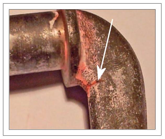 and it arrived more or
less by return post, so no complaints about the service. Now to use what I
had bought. I removed the steering arm from ‘Jo’ pretty easily, remembering
when to use the big copper headed hammer! Having done that I degreased and
paint stripped it. The final preparation was to give it a complete clean
with the supplied aerosol solvent. There were no visible cracks at this
stage. Anyway, I then applied the dye and left it so soak in for about half
an hour. After that, in accordance with the instructions, I cleaned off the
excess dye and sprayed with the developer, which leaves a white chalky
deposit on the surface. Slightly to my consternation, but perhaps not real
surprise, a crack appeared clearly, as in the picture. Mike
Johnston.
This article has been taken from the Isle of Wight
Newsletter with many thanks.
and it arrived more or
less by return post, so no complaints about the service. Now to use what I
had bought. I removed the steering arm from ‘Jo’ pretty easily, remembering
when to use the big copper headed hammer! Having done that I degreased and
paint stripped it. The final preparation was to give it a complete clean
with the supplied aerosol solvent. There were no visible cracks at this
stage. Anyway, I then applied the dye and left it so soak in for about half
an hour. After that, in accordance with the instructions, I cleaned off the
excess dye and sprayed with the developer, which leaves a white chalky
deposit on the surface. Slightly to my consternation, but perhaps not real
surprise, a crack appeared clearly, as in the picture. Mike
Johnston.
This article has been taken from the Isle of Wight
Newsletter with many thanks.
A precautionary note regarding the fitting of the
There are two types of
snail
adjusters in use on Morris braking systems. The smaller type is used
on the front brakes because there are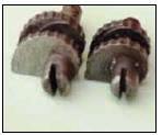 two leading shoes !! The rear has only
one leading shoes so a larger snail adjuster with greater lift because there
is only one in the rear brake. If a small adjuster is fitted to the rear
brake it will barely lift the shoe to a contact point for the brake shoe
with the drum leading to virtually all the braking on the front axle. Take a
look at your hydraulic brakes if you are NOT aware of this technical
feature. You may find a problem that you were did not know you had.
George Mooney DA7C
two leading shoes !! The rear has only
one leading shoes so a larger snail adjuster with greater lift because there
is only one in the rear brake. If a small adjuster is fitted to the rear
brake it will barely lift the shoe to a contact point for the brake shoe
with the drum leading to virtually all the braking on the front axle. Take a
look at your hydraulic brakes if you are NOT aware of this technical
feature. You may find a problem that you were did not know you had.
George Mooney DA7C
CRANKCASE/BLOCK
REAR NUTS: I always seemed to have difficulty getting the back
nut to the Crankcase/Block really tight, there seems to be so little room to
get a spanner on and or to move round. So my solution was to use one of the
'long' nuts from the tappet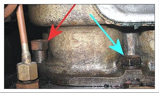 area (OK - I actually bought some more) to take the
top of the nut into an area where there was more room around the nut to get a
1/4" W - 5/16" BS ring spanner on. However, even then I had to thin down the outside of the ring to ensure
it went on OK. The photos show the difference in height.
With thanks to Sandy Croall (Cornwall A7C)
area (OK - I actually bought some more) to take the
top of the nut into an area where there was more room around the nut to get a
1/4" W - 5/16" BS ring spanner on. However, even then I had to thin down the outside of the ring to ensure
it went on OK. The photos show the difference in height.
With thanks to Sandy Croall (Cornwall A7C)
° When you realise there may be a little too much play in
the steering, don't think the worst. Frequently the problem lies with the
Draglink ball and cup system in the
Drag link bar. As the ball and cups wear they 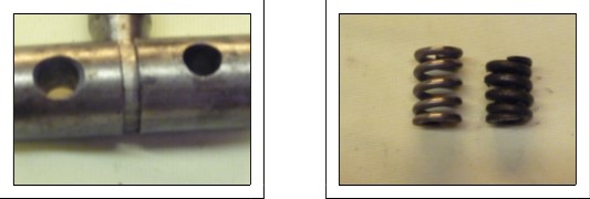 need not necessarily require replacing
unless the gap between the cups has closed completely. If there is still a gap
the problem could be improved with new springs. The illustration shows a worn
spring and a new spring. Replace the springs and the situation is likely to
improve dramatically. Don't ignore the problem. Fix it yourself if you can, or
ask for help from member services or a friend. If, after new springs are
fitted, the play is still too severe then look into the matter further until
the problem is identified. George Mooney
need not necessarily require replacing
unless the gap between the cups has closed completely. If there is still a gap
the problem could be improved with new springs. The illustration shows a worn
spring and a new spring. Replace the springs and the situation is likely to
improve dramatically. Don't ignore the problem. Fix it yourself if you can, or
ask for help from member services or a friend. If, after new springs are
fitted, the play is still too severe then look into the matter further until
the problem is identified. George Mooney
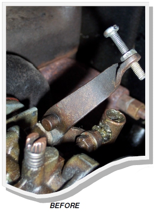
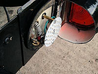
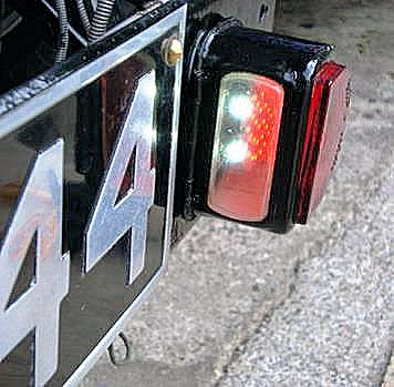
KEEPING TABS ON SERVICES: Not so much a technical tip, more of a reminder! I am not getting any younger and being the privileged owner of more than one Austin 7, it is not always easy to remember when the various mechanical and lubrication checks were last carried out on each vehicle! I find it very useful to keep a notebook in the glove box of each car noting the date and mileage of any works carried out on each vehicle together with reminders of jobs such as brake re lines (and tax date reminders etc) that might be due in the future. So when I think back, was it maybe 2 months ago when I last checked the axle oil, my little book can then tell me it was in fact 6 months ago! I had better check the level to avoid VERY expensive repairs!!! Gary Munn
TONNEAU
COVER ZIPS
-
HARDY SPLICER PROP FLANGES: Hardy Spicer propshafts can only connect in two positions. It is not possible to release the bolts and turn through 90 degrees as the fixing holes permit only 180 degree rotation on the flanges. To set the splined sleeved end at 90 degrees different to the fixed rear requires removal of the sleeved unit and refit at a new position by disengaging from the splined shaft and re engaging at the desired position. George Mooney DA7C
-
RAD COWL RIVETS: the correct size of rivets used to attach the neck to a brass radiator cowl for an Ulster re-build are 1/8" dia x 1/4". Best to use copper round head ones. Many thanks to Willie McKenzie
OIL PUMP
When you assemble your oil pump
don't forget: radiused shoulders to the top, no gasket under the cover
plate.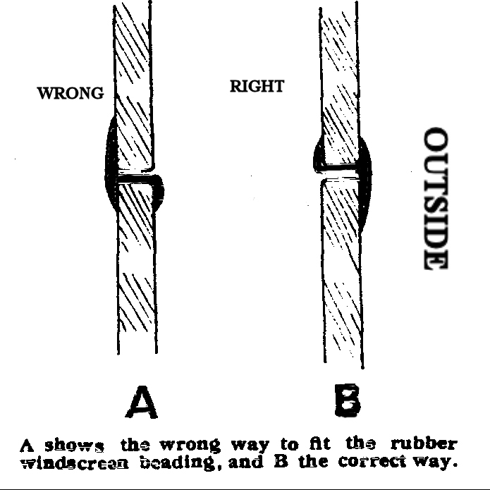
replacement windscreen glass can be obtained from Tower Glass, Yeomans Industrial Park, Yeomans Way, Bournemouth, BH8 0BJ Tel 01202 518555 for approximately £30, glass cut to your template and being a flat piece of glass they are not too difficult to fit. Douglas.
WASHING THE BABY: When washing your pride and joy, do not simply wash the visible coachwork but get your hose or jet wash and thoroughly spray the underside of all the wings and the running boards to remove all mud and importantly salt that has been picked up from the road. Especially important is around the front wing stays to prevent build up between wings and stays. This also gives you the opportunity to inspect the underside and reapply protection as required. Gary Munn
GEAR STICK RATTLE:
Wrap one turn of electrical
insulation tape around the cup at the base of the gear stick under the
cover plate, so it stuck to itself, then folded the top of the tape over
the cup rim. Although this stopped most of the noise the cover plate
still rattled against the gear stick itself, so again one turn of tape
around the base of the gear sti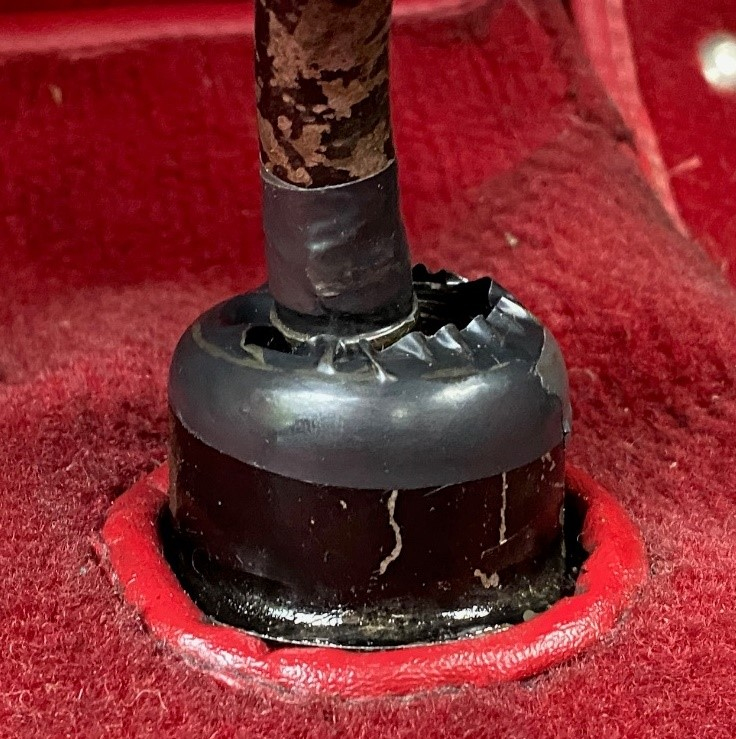 ck
still allowed the cover plate to slide down but no
ck
still allowed the cover plate to slide down but no
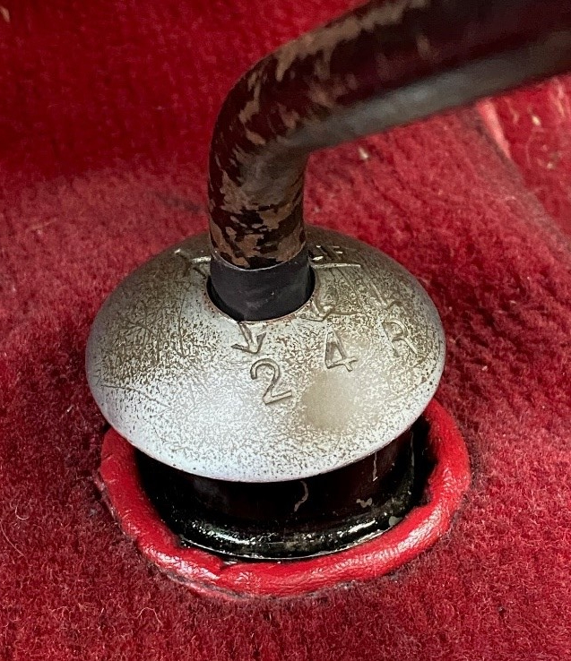 more
rattles. Nick Kidd DA7C
more
rattles. Nick Kidd DA7C