RP SLIDING ROOF
Hugh Barnes Cambridge A7 Club with many thanks
*See update at end
The previous owner of my car, obviously fed up with a rotten and leaking roof, had removed quite a lot of it and replaced it with a galvanized sheet, sealing the sliding roof up in the process. Ray Walker had helped me make a rough and ready improvement in the Seventies by fabricating the missing rail portion, enabling the roof to open again, though it was never really right as it would all too often prove in the pouring rain! Clearly, something had to be done. To help, I had bought a new set of rails and sliding panel from the Seven Workshop some years ago, though that needs the woodwork adding to it. These had been assembled onto the car and I was feeling quite pleased with myself. It was only when Lance dropped by one evening to see how I was getting on with the re-build he commented "of course, you're missing a part of the roof structure, and it doesn't go in like this anyway!" At that point I realised that I hadn't a clue how it went together and it all had to come out again!
I'd better explain the method
of construction first as, without an understanding of how the thing fits
together, the following parts of the article would be rather (even more?)
confusing. Originally the roof was completely constructed and covered off the
car and dropped and fixed into place as a final act. Hence, it’s one of those
jobs where regular checking that everything is going to plan and fits where it’s
supposed to is invaluable as the job progresses.
To remove the roof from the car it is necessary to
undo the screws from inside the car which pass through metal strips surrounding
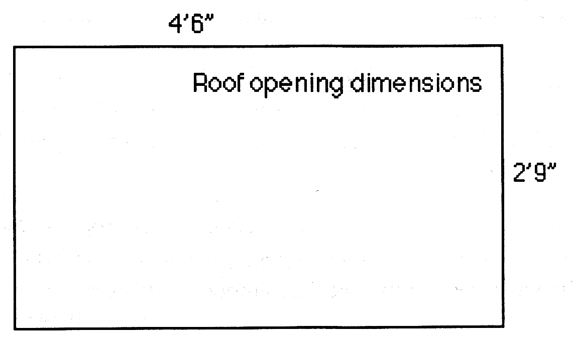
the roof opening up into the wooden framework. With the roof removed, one is
left with a large rectangular hole that everything should drop snuggly into.
Edging this opening beneath the metal of the body is part of the wooden framing
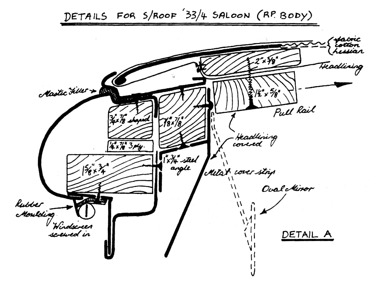
which strengthens the body of the car. Round the top surface of the bodywork is
a recess that the parts of the roof sit down into, bedded on a bead of mastic.
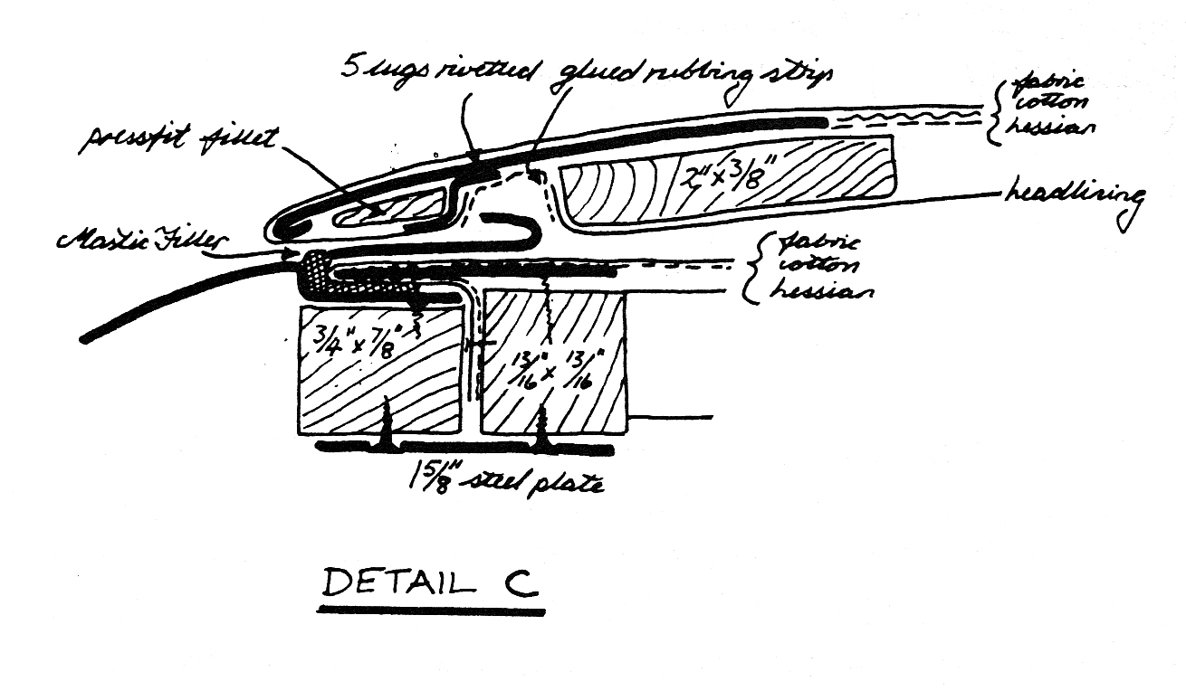
This creates a watertight seal to the whole thing. (At this point, it
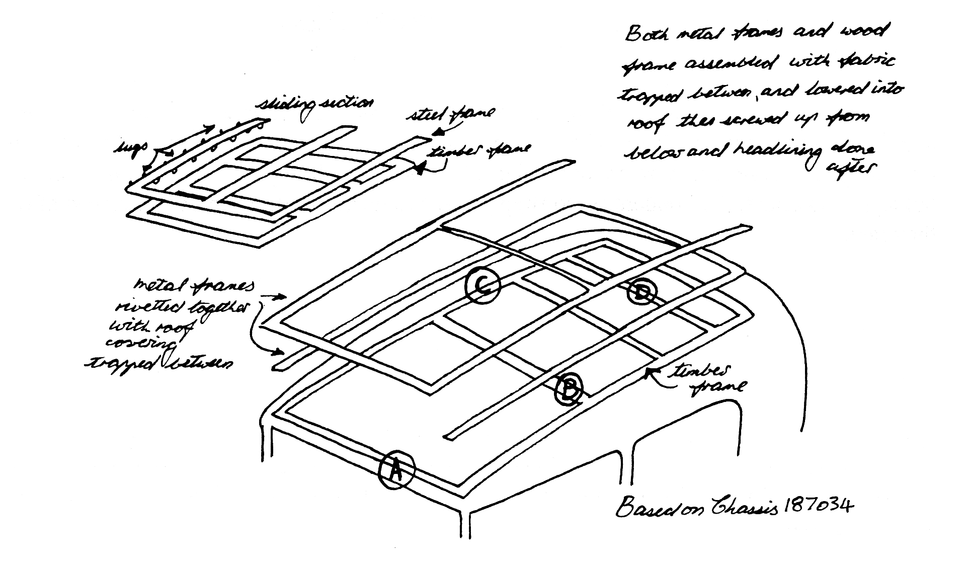
might be a good idea to study the drawings, particularly cross-section C)
After having stripped the old covering, fungus, birds’ nests etc. from the roof of your car, you will be left with three basic components:
1) The
channel sectioned steel framework
This serves as the runners for the sliding panel and
doubles as guttering around the roof opening. The size of this frame is governed
by the size of the recessed section of the roof.
2) The fixed wood and steel framework
.
The metal work is a simple
shape made from three strips of flat steel which go across the rear of the car
and down the sides. They finish lined up with the rear edge of the front of roof
opening, i.e. just above the windscreen. This was the piece I was missing
initially, but the metal was easily purchased cut to size for about a fiver and
welded up by a pal of mine. Dimensions will be arrived at from the opening but
must in essence be the same as the Rail Portion. These strips are screwed to the
wooden frame.
The wooden frame has to be made to be a snug fit in
the opening, but leaving a suitable gap for the roof materials to wrap round
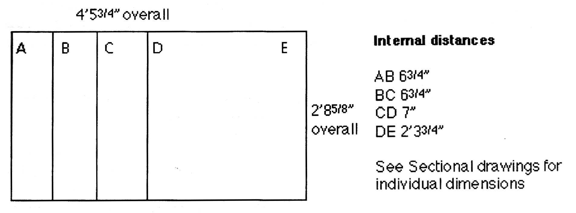
when covered. The front and rear rails are curved to match the line of the body,
but the three central rails are straight, thus giving a 'flat' roof. This is
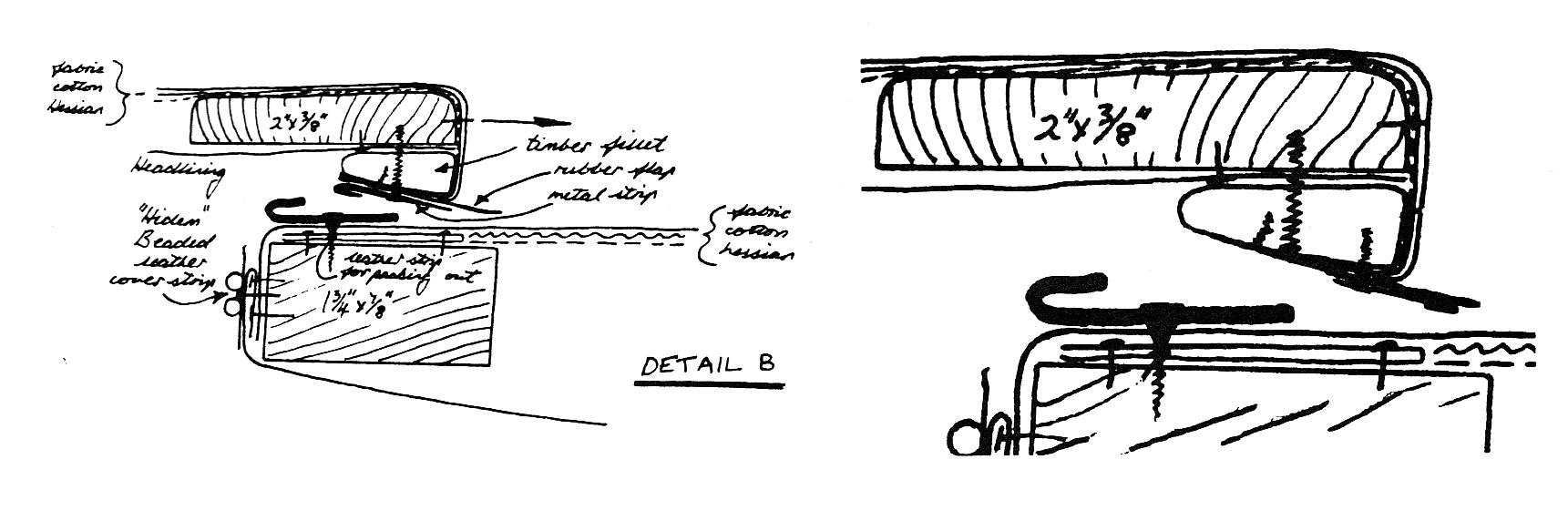
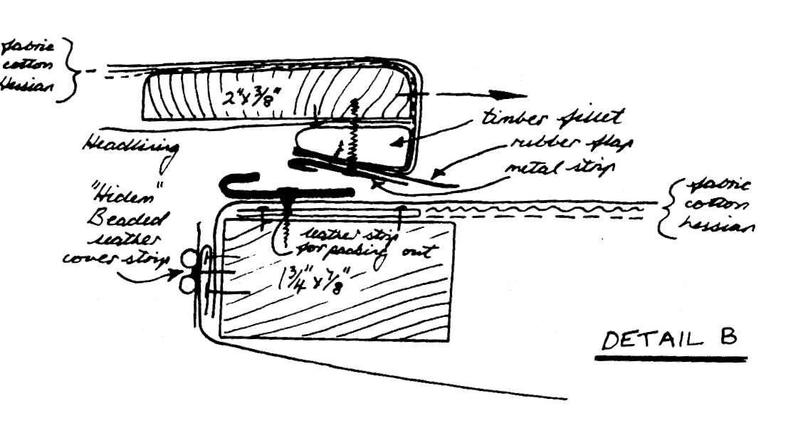
important as the rubber flap screwed to the back of the sliding part presses
against this surface (See Detail B). Overall dimensions again will be determined
by your car but those on the drawing are taken from my frame as a guide.
3) The sliding panel.
This again consists of a wooden framework together with a shaped steel pressing that screws onto the wood leaving an overlap. In addition, two thin strips of wood are clipped inside the edge of the metal pressing giving a point where the external covering material can be fixed. Hopefully, the sectional drawings will give you details of the construction - Detail C being the relevant one here.
When restoring a roof, the chances are you will have parts to base the reconstruction on. But, if like me, you are missing parts, the wooden frame is constructed so that it drops into the opening with just enough of a gap to be filled by the roof lining materials that will be pinned to the side of it. The three-sided metal frame screws to the wooden frame and is sized such that there is an overlap of some 7/16". The covering material is stretched over this before pinning to the wooden frame. I had already purchased what purported to be sufficient material (black external quality Vynide) to cover both the wooden frame and the sliding panel. However, this turned out to be enough to cover the rear portion of the roof (rails A to D on the diagram)
 and
and
the sliding panel only, leaving D to E uncovered. This, although possibly the original method, didn't strike me as quite right as this didn't leave a perfectly flat surface on which to sit the channel section (important if you want to be sure of a watertight joint). So, I bought some more material, 1½ times the size of the roof, which meant I was able to cover the entire wood and steel frame (from rails A to E) with no seams and enough left over to cover the sliding panel. The material between rails D to E is, of course, cut from the opening, leaving enough material to pin down inside the opening of the roof. This then gives a continuous flat surface on which to set the channel section, again bedded on a smear of mastic. After speaking to other Club members that have done this job, this may be a bit of overkill, but having spent some years with water dripping down my neck when it rains, I wanted to make sure this time!!
Originally, the channel section was rivetted to the lower metal frame, through the covering material though I decided this was unnecessary and screwed it down through the lower metal rail and into the wooden body framing that surrounded the opening in the roof. If the original method is followed, the whole lot, which is now a complete roof, would be dropped into the opening after a bead of sealant has been spread round the recess in the metal of the body.
 The
The
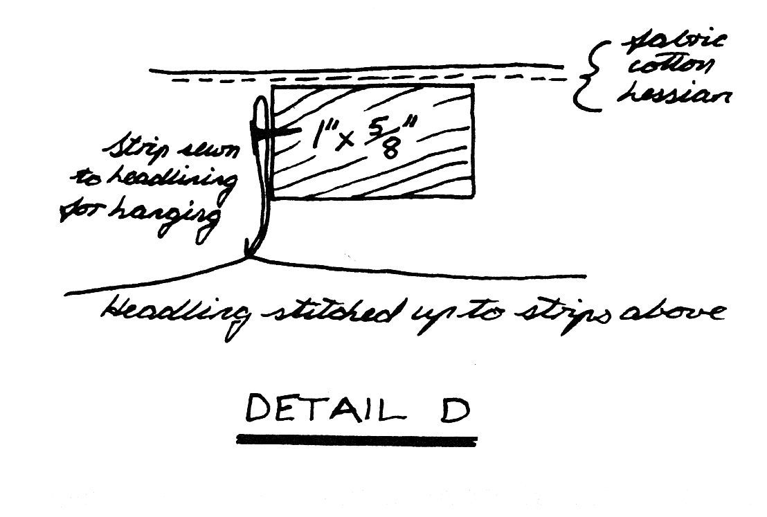
final act is to screw up from the inside of the car through a metal strip which is in part screwed to the wooden frame integral with the body, this then pulls the roof down into place. Screwing the rail section down means the wooden frame and lower metal portion can be covered and set in its place in the car first.Hopefully, you can see from the diagrams, the basic method of covering the roof. All the external surfaces have three layers of material. First a piece of hessian is drawn tightly across the panel and stapled round the edges into place. This is there to support the next layer, a layer of cotton wadding to give a smooth finish to the job, concealing any unsightly projections such as screw heads etc. It also gives a pleasing 'padded' look. Be careful not to overdo the thickness however, we're not trying to create the look of a padded cushion! Finally, the layer of Vynide or Everflex (my preferred material) is stretched over the entire piece; in the case of the wooden frame, it is stapled to the sides of the frame and in the case of the sliding panel, stapled to the wooden fillets attached to the underside of the metal piece. When covering the panel, a thin layer of wadding is placed in each of the 6 holes in the framework, then a thin layer of wadding is placed over the entire panel before covering with the Everflex. This has to be glued and or tacked to the underside of the panel. As will be seen from diagram B, the rear of the panel has a further triangular fillet of wood tacked across it, which the exterior covering is wrapped round. Note, this fillet has trapped between it and the panel the roof lining, so this part must be trimmed with that at the same time as the external covering is completed. On top of the fillet is screwed a metal piece which traps a rubber seal which I can only assume is a draught seal, though, in rainy conditions, it does perhaps prevent a rush of water swamping the guttering across the rear of the roof opening under braking.
*SLIDING ROOF UPDATE BY HUGH BARNES
After trying last time to
write the definitive description of an RP roof restoration, I find myself,
somewhat sheepishly, penning an erratum. At the point of writing the last
article, the roof was all together and just awaited dropping in the car on its
bed of sealant and screwing into place. When that had been done, horror of
horrors, I found it wouldn't shut!! Not only that, the sliding action had
tightened up and it was very difficult to move back and forward.
Closer examination revealed that the cause of the
former problem was the draught seal at the rear of the sliding panel fouling the
cross piece between the roof rails, whilst the latter was caused by too great a
thickness of felt having been riveted to the lugs on the panel. Nothing else for
it, time to remove the panel and remedy the problems. Easy one first....
The felt pads riveted to the
lugs on the sliding panel had been created from off cuts of the felt strip used
to go between the body and chassis. Basically, they were far too thick. On
examination of the remains of the original, the felt was found to be much
thinner. With the felt completely removed, the sliding action could be seen
better and I realised that the lugs did little more than loosely hold the panel
in place whilst, at various points in its travel, the panel actually rested on
the top of the rails. Although this didn't seem right, it seemed the only way
the system would work. Again, examination of other Member's cars showed the same
symptoms.
I did replace the felt on the underside of the lugs,
but with much thinner material and this time glued with EvoStick. which seems
to do the trick. Result, the roof now slides back and forth with some ease.
The next problem was not quite so easily overcome. On
inspection, the roof was found to bow from one side of the car to another, i.e.
quite a gap in the centre of the car between the panel and the cross rail to
almost none at the edges (looking at other cars seemed to give the same shape).
Having slavishly followed the previous plans, it was clear they were not quite right. The triangular wooden fillet shown in diagram 'Detail B' clearly had to be tapered to take account of differing amount of gap between the panel and the cross rail. Having taken the rubber seal strip and its metal support and the wooden fillet off the roof panel, 20 minutes work with a plane had the fillet to the required shape and mounted back on the panel. A quick check back on the car showed that we weren't suffering the fouling problems of before.
Having looked at other cars and being logical about what was required, I decided a further problem with 'Detail B' was that the metal support for the rubber seal was shown a) back to front (i.e. the folded edge should point to the rear of the car), and b) it couldn't fit so far 'into' the roof and needed to be mounted such that it protruded out from under the panel. To remove any further likelihood of creating a structure that was too thick, I decided to stick the rubber seal onto the metal strip, rather than trapping it between the wooden fillet and the metal strip.