 .
.THE PETROL GAUGE
Construction, assembly, faults and remedies
by H Allarton
THE electric petrol gauge is
now practically a universal fitment on all cars and motor cycles, and the
majority of designs are identical in principle, although they may vary in
detail.
There are two units which make up the complete
instrument: one is the glass-fronted gauge on the instrument panel, and the
other the unit mounted in the tank, usually at the top, but occasionally in one
side or end
.
The Tank Unit
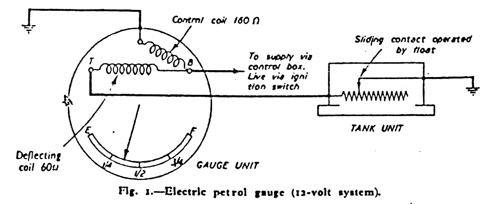
This, as shown in Fig. 1, consists of a float
mounted on the end of an arm which is pivoted on a spindle and arranged so that
vertical movement of the float is transmitted to a second smaller arm which is
in contact with, and moves horizontally over, a length of resistance wire wound
on a former. As the level of petrol in the tank rises or falls so the float does
likewise, and this movement causes the second arm to vary the effective length
of the resistance wire. The resistance wire is connected in series with the
deflecting coil in the gauge unit, as can be seen from the circuit diagram, and
thus the magnetic field emanating from the deflecting coil is made weaker or
stronger, depending upon the amount of resistance in the circuit.
The whole unit is usually mounted in a die-cast
housing which is flanged to fit the tank and which has an inspection cover for
access to the resistance wire and moving contact. The unit usually has only one
terminal which is connected to the gauge on the panel (terminal T), the moving
contact bring earthed to the cam and thus completing the circuit.
The Gauge Unit
These (also shown in Fig. t) naturally vary
considerably in external appearance, since very few can have identically styled
instruments, but they consist in essentials of a pair of coils wound on formers
with soft iron cores. The coils are disposed so that the magnetic fields they
produce, when current is passed through them, influence a soft iron armature
carried on a spindle. Attached to the spindle is a pointer which moves over a
graduated scale. One coil is called the control coil and the connections are so
arranged that the full battery voltage is always applied to this coil when the
ignition switch is on. The other coil is called the deflecting coil, and the
voltage applied to this coil is proportional to the amount of petrol in the
tank, since in series with it is the resistance wire in the tank unit, the
effective length of which is varied by the moving contact which in turn is
operated by the float.
How the System Works
When the petrol tank is full, the float will
have operated the sliding contact on the resistance in the tank so that all the
resistance wire is in circuit. The current flowing through the deflecting coil
will therefore be a minimum and the magnetic field from it will therefore be at
its weakest. On the other hand, the current passing through the control coil
will be a maximum since the full battery voltage is always applied to this coil
when the ignition switch is on. The magnetic field from the control coil will
therefore be very strong, and the soft iron armature will be attracted to its
maximum extent, so that the pointer will indicate " full" on the gauge.
As the level of petrol falls the float will also fall,
causing the moving contact to move over the resistance, thus reducing the amount
in circuit. The current in the deflecting coil will thus increase and there will
be a corresponding increase in the strength of the magnetic field from the
deflecting coil. Since the coils are so arranged that their magnetic influences
on the soft iron armature are in opposition, the armature and therefore the
pointer will be deflected more and more from the "full" position until, with no
petrol in the tank, and therefore no additional resistance in the deflecting
coil circuit, the effects of each coil on the armature cancel each other out and
the needle shows "empty" on the scale.
Tracing Faults
The petrol gauge as described above is
intended solely to give an indication of the amount of fuel in the tank and was
never designed as a means of calculating fuel consumption. Provided that this
fact is remembered, the electric petrol gauge is extremely reliable and will
usually continue to work satisfactorily without attention for many years.
Irregular or false indications when they do occur are usually due to faulty or
loose connections in the wiring; the gauge and tank units will seldom be found
at fault.
Faults can very readily be localised and corrected by
following a simple procedure. Reference to the circuit diagram will be helpful
in tracing the following faults. Figures given are for 12-volt systems.
No Reading
Any open circuit in the control coil
connections will result in no reading at all on the gauge, regardless of the
amount of petrol in the tank and the most likely cause is therefore a broken
connection between the gauge (terminal B) and the ignition switch or between the
ignition switch and the control box. A blown or loose accessories fuse should
not be overlooked in this case.
In the unlikely event of the trouble not being located
at any of the above points, then the control coil in the gauge must be
suspected. To check the coil properly, its resistance should be measured if
suitable equipment is available. The control coil should have a resistance of
the order of 160 ohms.
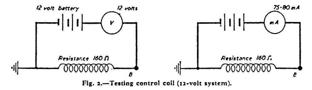
However, a simple test can be made using only a
voltmeter, and this will at least determine whether or not the coil is faulty.
Any fault which may be found will almost certainly be due to a broken connection
or badly soldered joint.
If a voltmeter is connected between the positive
terminal of a 12-volt battery and terminal B on the meter, and the negative
terminal of the battery is connected to the case of the meter, a reading of 12
volts should be shown on the voltmeter if the coil and connections arc sound.
Alternatively, if a milliammeter is available and is connected in series with
the control coil and a 12-volt battery, a reading of 75-80 mA will be obtained
if all is in order (see Fig. 2).
Continuous "Full"
Reading
An open circuit in the deflecting coil
circuit will result in the gauge always showing " full," irrespective of the
amount of petrol in the tank. Points to check in this case are:
(1) the wire between terminal T on the
gauge unit and the single terminal on the tank unit;
(2) the earthing connection of the tank
unit;
(3) the sliding contact which moves over
the resistance wire.
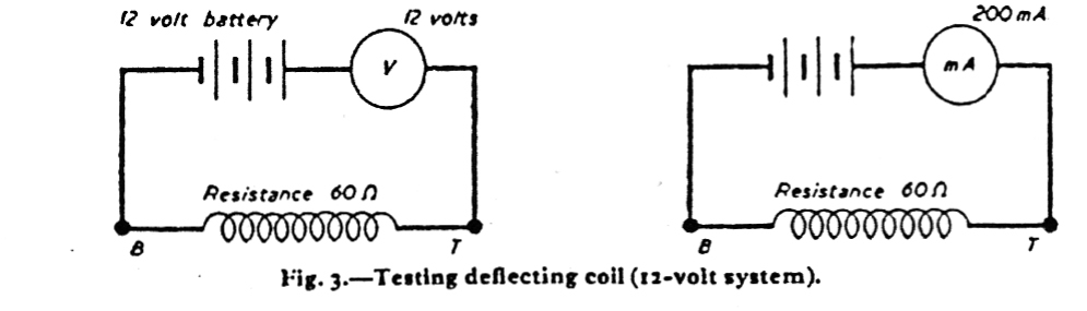
If all these are proved sound, then the deflecting
coil in the gauge unit must be checked in the same manner as the control coil.
Its resistance is approximately 60 ohms, and a 12-volt battery connected
across it will cause a current of 200 rnA to flow (see Fig. 3).
Intermittent Reading
An intermittent reading will usually be found
to be caused by a faulty contact between the sliding contact and the resistance
in the tank unit; in this case the contact arm and the surface of the wire over
which it moves should be cleaned with fine emery paper. Care should be taken to
see that the arm moves freely and is in contact with the wire throughout its
movement.
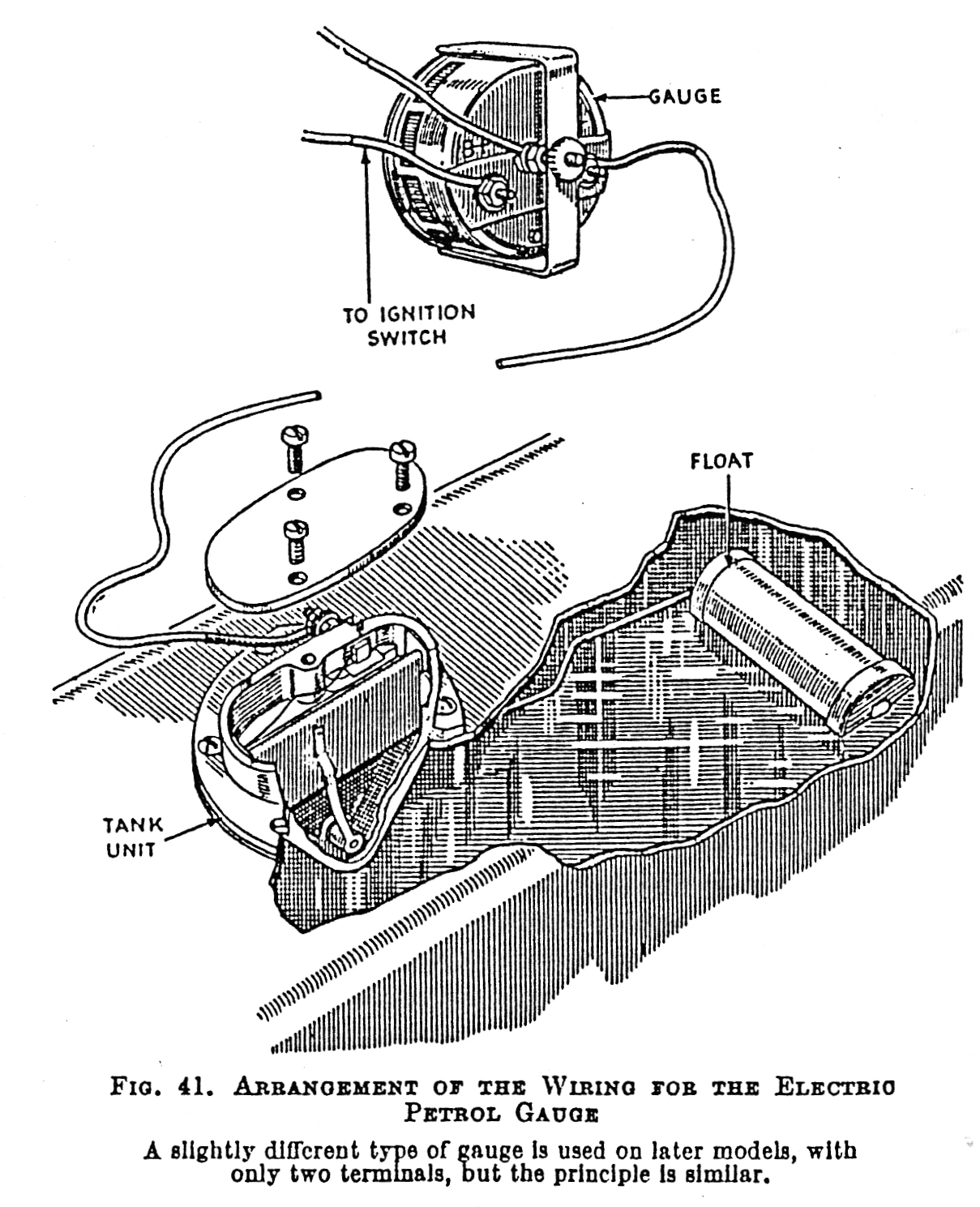
The points at which a loose or broken connexion might
put the gauge out of action will be seen from Fig. 41. It is important that both
the gauge and the tank unit should earth properly. The cable from the tank unit
may be earthing at some point if the gauge shows a full tank without cause. If
it is the tank unit terminal which is earthed, the unit will require repairing.