NEW BRAKES ON THE SEVEN
A DESCRIPTION OF THE SEMI-GIRLING SYSTEM
From the Austin Magazine, November 1936
IN the Austin Magazine for June and July last the
adjustment and maintenance of the braking system then employed on the Austin
Seven was described in detail. Since that time Girling-type brakes have been
incorporated in the design of the Seven, and to these the following particulars
strictly apply, being at the same time, in respect of all general braking
considerations, supplementary to the previous articles on this subject.
Although basically the two systems are alike, the
layout of the new semi-Girling system is an improvement on that it supersedes.
In both, the application of the pedal or the hand lever results in the rotation
of cross -tubes from which the braking effort is transmitted to the shoes by
levers and cables. The chief advantages of the new system are the increased
efficiency of the mechanism employed for expanding the shoes into contact with
the drum, which ensures more effective braking, the accessible individual
adjusters behind each brake, and the dual cross-tubes whereby the front and rear
braking is automatically compensated and proportioned.
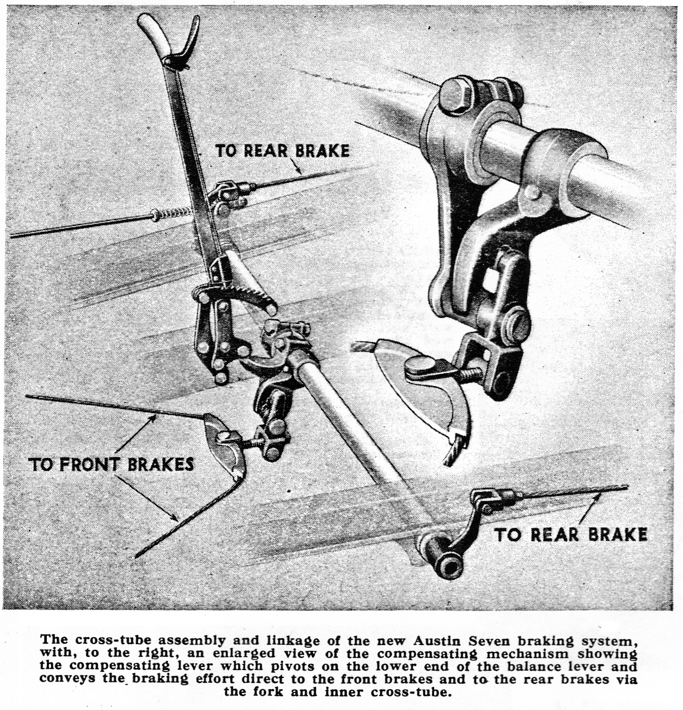
Referring to the diagrammatic layout of the new compensating system, it will be seen that the brake pedal rod is connected to a lever on the outer cross-tube. The other end of this tube at the centre of the frame carries a balance lever on which is freely mounted at its lower end a short compensating beam. It is from this beam that the braking effort is distributed to the front and rear brakes. For the front brake operation a swivelling quadrant, connected to the lower end of the compensator beam, pulls the single cable that applies both front brakes. For operating the rear brakes, the upper end of the beam engages with a forked lever extending from an inner cross-tube which carries at its extremities the levers for the rear brake cables.
The accompanying illustration
shows this design in detail, and reveals how the inner cross-tube, which
operates the rear brakes, derives its movement from the outer cross-tube via the
balance lever and compensating beam.
The operation of the brakes by hand is through a lever
fixed directly to the inner cross-tube. Gentle application of the hand lever
results in the braking effort being first transmitted to the rear brakes, and
the front brakes come into action when the clearance of the compensator beam in
its fork has been taken up by the initial movement.
From the cross-tube levers the brake cables connect to
the levers on the actual brakes. These rotate the cams to force the
shoe-operating plungers apart and move the shoes into contact with the inner
surface of the drums. It will be realised that this design varies from the usual
Girling layout in that the shoe-operating plungers are actuated by cam and lever
instead of by a wedge (or cone) and rollers.
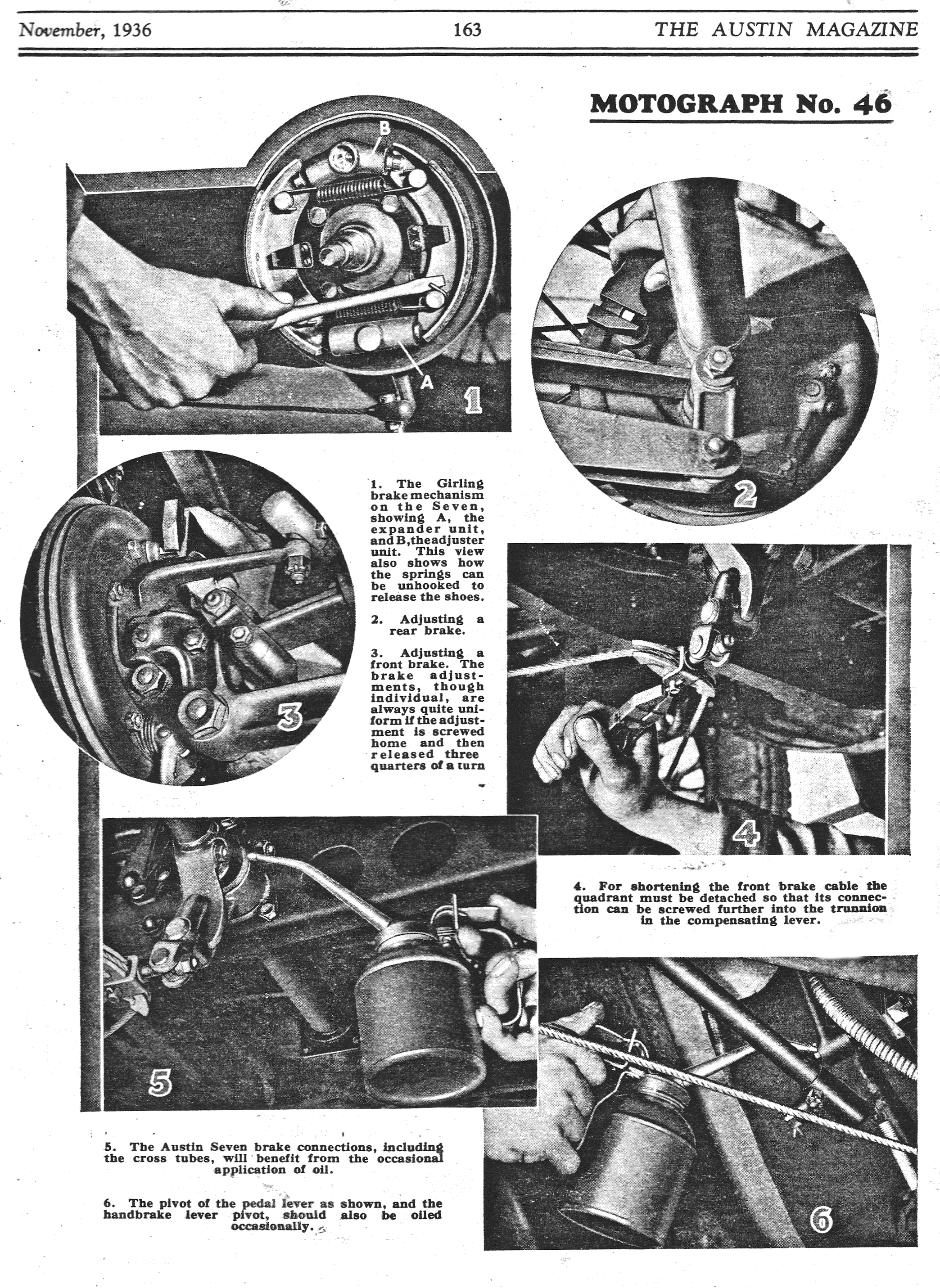
The functioning of the Girling
design of shoe adjusters has more than once been described in these pages, but
for the benefit of Austin Seven owners, not fully conversant with this type of
brake, we will give a short description of the adjustment mechanism.
The complete brake consists of two Girling type steel
shoes carried between two units attached to the back plate. These shoes are held
off and rendered self-centring by release springs of the usual type. One of the
shoe-supporting units houses the actuating cam and plungers mentioned above. The
other, or adjuster unit, supports the other ends of the shoes on inclined
plungers which are grooved to take the shoe webs. The inner ends of these
plungers bear directly on the adjustment cone which has four flats on its
surface. The cone screws through the adjuster housing and its outer end is
squared so that it can be turned with a spanner to advance it against the
plungers, which are then forced further apart to move the shoes towards the
brake drum. The squared surface of the cone provides flats and intermediate high
points so that when the shoes are adjusted until they are actually engaging with
the drum, under the influence of the high points on the cone, a three-quarter
turn back of the cone gives the correct clearance between the friction surfaces.
This clearance is very small, and the self-centring action of the return springs
ensures that it is the same for the entire arc of contact with the drum.
Further, due to the inclination of the adjuster plungers, the shoes are adjusted
in such a way that the true bedding of the linings is not affected.
For adjusting the new Seven
brakes the car must be on level ground with the hand-brake off, and there is no
need to jack up. Each adjuster can be turned with a spanner in a clockwise
direction, and the correct setting can be felt and heard (by three clicks) on
the return movement which gives the necessary clearance after the shoes have
made contact with the drum. This attention is the same for all the brakes and
automatically ensures their uniform adjustment.
The adjustment of the shoes as described above returns
the pedal and hand lever to their original positions, and thus there is no
provision for separate adjustment of these controls. But in the event of unequal
stretch of the brake cables, as between front and rear brakes, the clearance of
the compensator beam in its forked lever, which must be maintained equal on
each side, may be affected.
This can be corrected by removing the forward ends of
the back brake cables and adjusting the cable length by screwing the fork
further on or off the cable or, in respect of the front cable, by removing the
pin securing the front brake compensating quadrant and screwing rearwards its
forked connection, afterwards replacing the quadrant securely. It must be
emphasised, however, that these cable adjustments are not an alternative to
brake adjustment; they are solely for correcting uneven stretch, which, in any
case, once the system has settled down, is not likely to be sufficient to
require attention except after very extensive periods of use.
With regard to maintenance, the new Seven brakes require very little attention. The pivoting point for the pedal lever, situated on the steering box, requires an occasional drop of oil, and the same applies to the hand-brake lever and the small roller which transmits the movement to the cross-tube. The cross-tubes themselves will also benefit from occasional lubrication, which can be applied to the felt washers on each side of the bearings and where the inner tube emerges from the outer. There are five of these felt washers in all. The actual braking mechanism of each axle requires no lubrication, being packed with grease when first assembled, which should last indefinitely.
Turning to the question of the brake linings themselves, these require just the same attentions as those on the superseded design of brake. We do not propose to deal with these attentions here, seeing that they were adequately covered in our previous article. Access to the linings can, of course, be obtained by removing the brake drum, which is secured by three screws, but if re-lining becomes desirable it will be found necessary, as hitherto, to remove the hub before the shoes can be dismounted, and for hub removal a special extractor is required.
Dismounting the shoes involves very much the same procedure as for the old type brake, namely, using a screwdriver or similar tool to unhook the return springs so that the shoes are free to come away from their mountings; but it should be emphasised that both shoes locate in plungers in the adjuster and expander units, and being retained by guide plates, they can only be pulled away from these plungers when free of their springs. When the shoes are clear the plungers will remain in position.
In re-fitting the shoes, the best plan is to connect them with one of the springs and remount them on the two adjusters and the two expander plungers before finally fitting the second spring, using a screwdriver or suitable lever to pull it over its anchor pin on the shoe.