MODERN FLASHER CIRCUITS:
hello
NUMBER 1 - ADDITIONAL 'ORANGE' INDICATOR LAMPS
I’ve had this article ‘on ice’ for some time but, unfortunately, the original copy has been lost. So many thanks to whichever A7 Club first printed it and thanks to Andy DeLuvian for his hard work in producing it.
Many owners are fitting flashing indicators to their cars for obvious safety reasons. Although strangely frowned upon by purists, in modern traffic conditions clear intention of change of direction is vital and our quaint, although loveable, semaphore arms are simply unsuitable. Too many road users these days are not expecting a little arm with a glowing bulb to pop out of the side of a car. These are especially difficult to see in daylight conditions. With the shorter daylight hours upon us now is the time to think about fitting up-to-date indicators. There are numerous suitable lamp fittings available these days. Often motor cycle indicator lamps can be modified and won’t look out of place. For those with the bigger Austins fitted with torpedo style front side lights a conversion is available with a white sidelight bulb and amber indicator bulb (12v). It is also fairly easy to make up your own using trailer type lamp fittings with suitable 6v or 12v bulbs depending on your system. Wiring them up is not a difficult task but to help those who are a little unsure of the procedure we are grateful for the following article supplied by our “Colonial Correspondent” which explains the working of the flasher unit (Fig. 1) together with an easy to follow wiring diagram (Fig. 2).
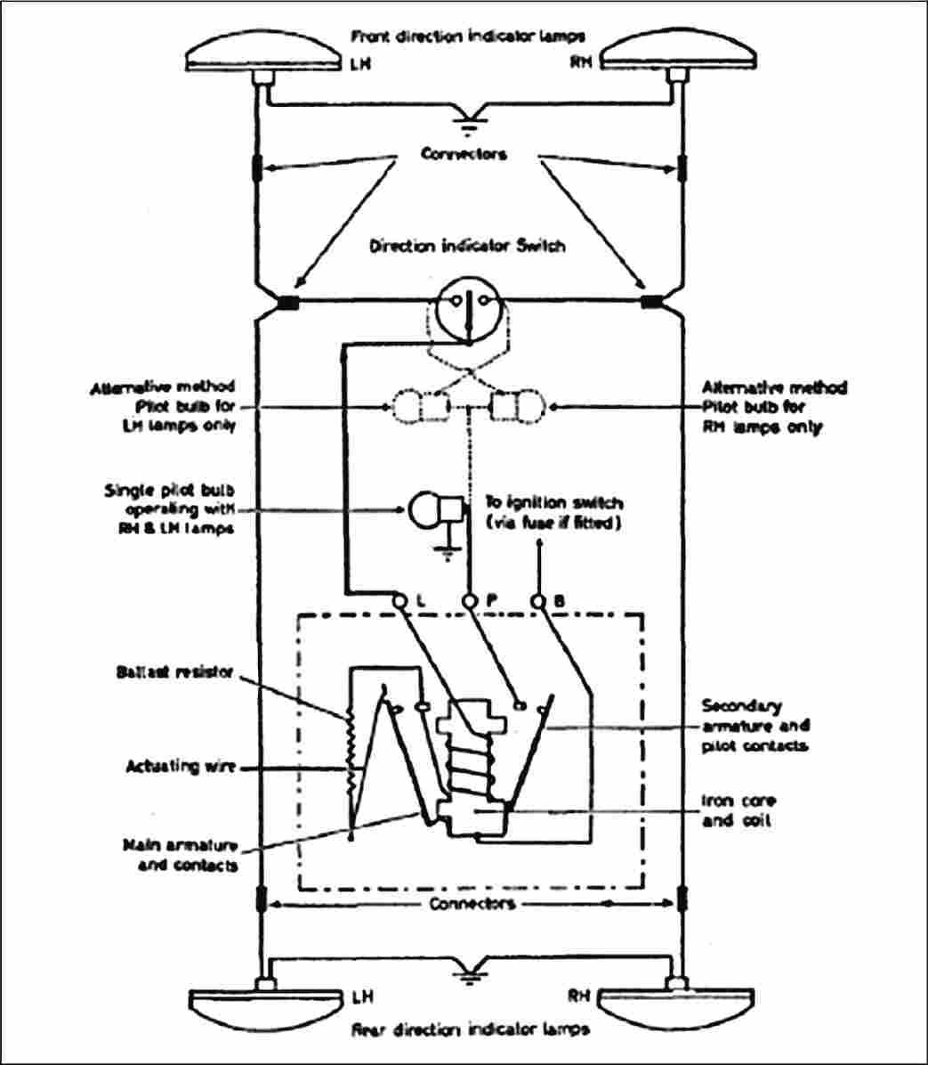
When the direction indicator switch is operated, a circuit exists between the battery, flasher unit and flasher lamps back to the battery. Current travels from terminal ‘B’ of the unit, through the actuating wire, ballast resistor, coil on the armature and through the flasher lamps back to the battery by way of earth. This current, which is insufficient, because of the ballast resistor, to light the lamps, causes the actuating wire to heat up and expand. It continues to do so until the wire stretches sufficiently to allow the main contacts to close. Once the main contacts are made the ballast resistor is effectively shorted out and without this resistance a heavier current flows by way of the main contacts. This heavier current passes through the armature coil and lamps which are then lit. At the same time, a magnetic field produced about the armature attracts the moving contact of the secondary armature and the circuit is made to the pilot warning lamp in the car. While this is happening there is, of course, no current flowing through the actuating wire and it begins to cool down. When it has cooled sufficiently the length and both pilot and main contacts separate. Current again flows by way of the resistor and the lamps are extinguished. This sequence continues until the turn signal is cancelled.
The ratio between lamps ‘on’ and lamps ‘off’ is usually about 50:50. The flashing rate in order to comply with regulations is between 60 and 120 operations per minute. The bulb filament rating is usually 21 watt for 12v systems. With a four-lamp system, the load will be 42 watts and similarly a flasher unit of appropriate rating must always be used. If a lower wattage is used on a 6v system the flasher unit rating must match. Failure to observe this rule will result in either too slow or too fast a rate of flash and, in the case of overloading, the flasher unit may burn out.
Andy DeLuvian
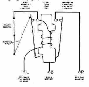
Fig. 2 A typical four-lamp flashing indicator circuit. If fitted, side repeater lamps would be connected to the feed wires of the main front lamps.
NUMBER 2 - FLASHERS WITH SEMAPHORES
(with thanks to the Morris Register Magazine)
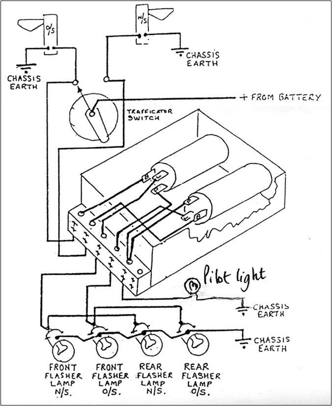
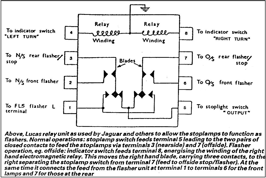
Fig. 1 Internal circuit of a Lucas Flasher unit showing connexions to battery, pilot light, and indicator lamps.
NUMBER 3A - DUAL FLASHERS RELAY (OLD TYPE)
NUMBER 3B - MODERN EQUIVALENT RELAYS
Here is an "update" that may be of interest to those of
you who do not want to add obvious modern flashing indicator units to their cars
using
the front side lamps and the rear brake lights. This is not an original idea of
mine as was used in the 1960s by (sorry) Morris Minors. They used a Lucas LB10
relay which although still available is a tad expensive at around £120, so
scouring the Internet I found instructions for an alternative using four relays.
After sorting through my electrical spares tin, I found some relays and produced
a functioning alternative.
The wiring may seem a little daunting, but it
looks worse than it actually is. An ice cream container was used to encapsulate
the relays and the flasher unit. This, with the top on, keeps everything nice
and dry. The bulbs I use are LEDs so a suitable flasher unit had to be
purchased. One other mod I carried out was to insert another relay on the feed
to my central rear stop tail light, which enables me to override this brake
light and switch it on as a rear fog warning light.
Although this modification as used on my special is for a twelve volt system,
there is no reason, with the appropriate relays for it not to be used on a six
volt circuit, using suitable six volt relays etc which are readily available on
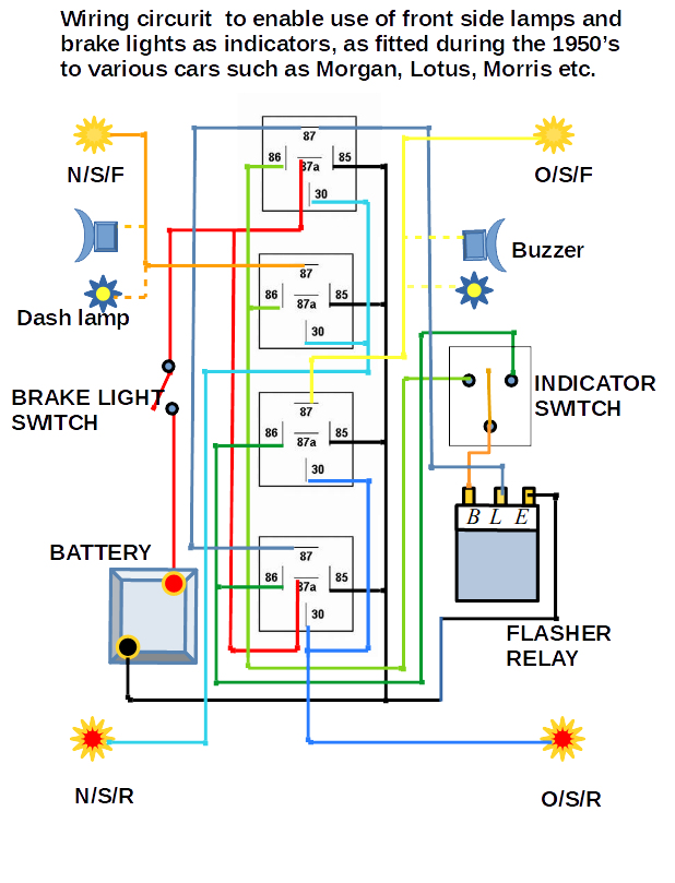
web sites This circuit diagram shows how, with the aid of four, 5 pin relays,
one can utilise the existing lights on the Austin Seven to act as indicators.
The front side lamps and the rear, brake lights become duel functioning units
acting as the "flashers" and thus eliminating the necessity to fit modern
lamps, although I would recommend L E D bulbs to reduce the load on the
dynamo, and give brighter lights. The four relays are mounted together along
with the electronic [ L.E.D. suitable] flasher unit, under the dashboard. The
indicator switch I used is from a fifties Austin A30 or similar, dash mounted.
In addition, I also incorporated dashboard warning lights and micro warning
buzzers, as the lights are not self cancelling.
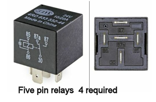
The five pin relays are
suitable for the purpose, only not using the 87a pins on the middle two, as
shown in the circuit diagram. The colour coding in the diagram is for clarity,
any colours can be used, but a note of the connections should be made to assist
in the eventuality of any maintenance being required.
Items required :--
4 x 5-pin ( switch over )
relays such as Hella 4RD 933 332 44, or 77 similar costing from about £7.00.
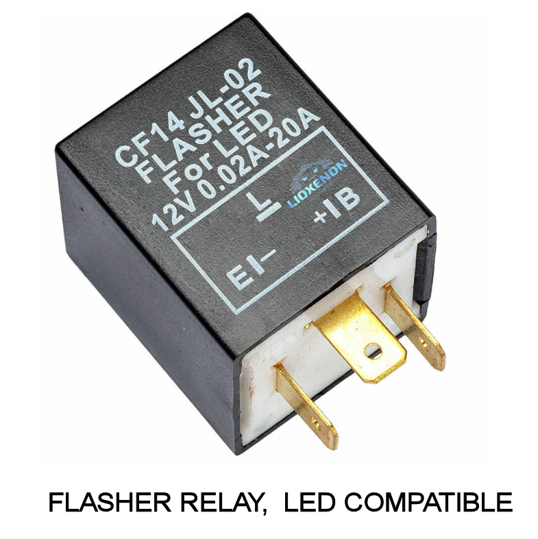
1 Flasher relay (LED compatible if appropriate ) such as CF13 JL-02. or similar
cost approximately £3.75.
2 Dashboard warning lights. A pair should cost
about £5.00
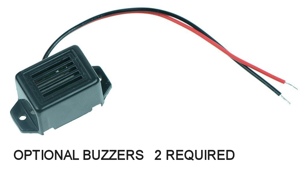
2 Warning buzzers (optional) various types at a cost of about
£3.50 each.
Peter Clayton DA7C
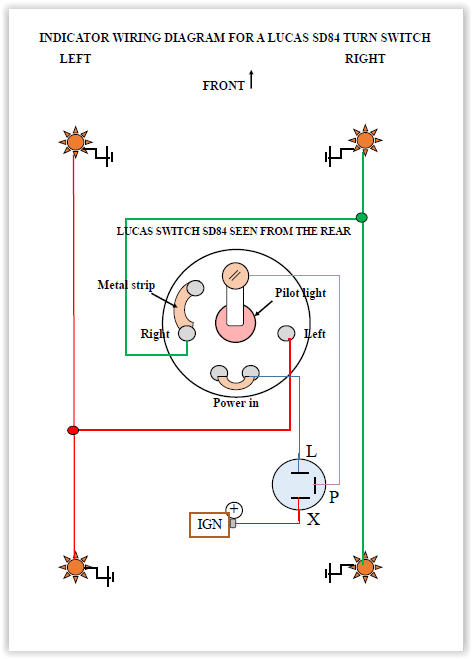
NUMBER 4 - LUCAS SB84 TURN SWITCH