FITTING THE ACCUSPARK A7
DYNAMATOR (ALTERNATOR) Model A12
By Vince Leek
This alternator is a replacement for Dynamos type C35a /
C35m and DEL as used on the Austin Seven from 1930 to end of production. It
cannot be used to replace the DF or DFL type used on magneto engines. The unit
comes complete with new gears and ready to fit. It is a 12 Volt regulated unit
capable of 45 Amps output. The output is positive, therefore it is only suitable
for cars converted to 12 volt with Negative Earth. (A 6 volt version may be
available in the future).
Wiring Circuit Diagram
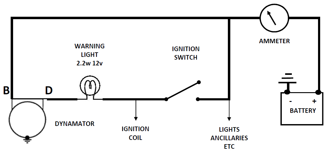 There
are two connections in a terminal block mounted on the dynamator case, B (+12v
output) & D (control). The case is the earth (third connection). You will see
that terminal B is connected via the ammeter to the positive post of the
battery. The terminal D is connected to the ignition circuit via the ignition
warning light. When the ignition is switched on a small current passes through
to the alternator via the warning light. Apart from lighting the bulb this
excites the alternator, and if the engine is running, the alternator will
produce an output and current will flow via the ammeter to the battery. At this
point the ignition light will go out and the alternator will continue to deliver
the appropriate charge. If the engine stops the output would cease and the
ignition light will come on again. Just like your modern car!
There
are two connections in a terminal block mounted on the dynamator case, B (+12v
output) & D (control). The case is the earth (third connection). You will see
that terminal B is connected via the ammeter to the positive post of the
battery. The terminal D is connected to the ignition circuit via the ignition
warning light. When the ignition is switched on a small current passes through
to the alternator via the warning light. Apart from lighting the bulb this
excites the alternator, and if the engine is running, the alternator will
produce an output and current will flow via the ammeter to the battery. At this
point the ignition light will go out and the alternator will continue to deliver
the appropriate charge. If the engine stops the output would cease and the
ignition light will come on again. Just like your modern car!
Fitting the DYNAMATOR to the car (applies to all
cars)
This is a simple operation as it fits directly into the existing dynamo
housing. Procedure. Disconnect the battery. Set No.1 piston to top dead centre
(tdc). Note position of rotor arm in distributor. Remove distributor. Note
connection of wires to dynamo (very important) remove dynamo. Fit Dynamator with
new gasket. Fit distributor with rotor arm in original position after applying
grease to the drive gears. Reset timing if necessary. (Note. Currently the long
fixing screws are 1/4 BSW Not BSF as original).
Connecting up to the car wiring
With the Dynamator there is no need for the cut-out. Consequently if
fitting to a 'Special' or where authenticity is not important the cut-out can be
discarded and the above simple circuit can be used. However if retro-fitting to
a standard car things become slightly more complicated. This is because owners
may want to retain the existing car wiring and warning light for authenticity,
and to have the ability to revert back to the original dynamo in the event of a
Dynamator failure, perhaps when overseas.
If you wire according to the instructions supplied by Accuspark, the cut-out
will still be in circuit, the points will be permanently closed and the control
winding will cause a drain on the battery. Although this is very small it is
undesirable and would eventually discharge the battery.
Disabling the cut-out and using the existing wiring is not very difficult. There
are four basic circuits used on the Austin 7. These are based on the four
different cut-out / switch unit used. The following instructions will put things
right, and the only tool you will need is a screwdriver! If you are unsure of
what to do then seek advice.
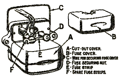
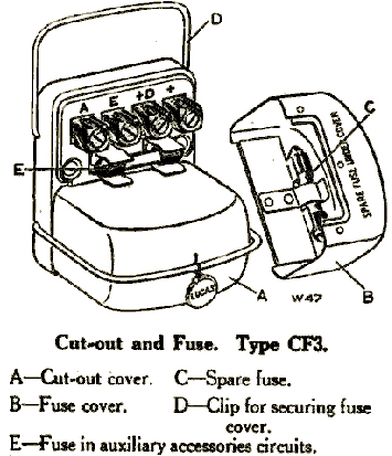
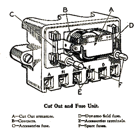
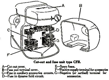
Images of cut-outs from Austin Handbooks (clock
wise from top left).
1929-1932 CF1,
1932-1934 CF3,
[1934 Cut out GFR (not shown)]
1934-1936 Ruby Cut out CFR
1936-1938 CFR2
THE FOLLOWING ASSUMES THAT THE CAR WIRING IS
CORRECT AS ORIGINAL and you can use the existing wiring where possible.
The Circuit modification diagrams below only shows wires to be altered please
check against full circuit diagram and your car.
1929/30 cars (cars using DEL dynamo/ CF1 cut-out
and SM5 Switch panel).
1. Fit Dynamator as above. Note positions of wire connections, very
important.
2. Connect the wire previously fitted to the ‘D’ terminal on the dynamo (this is
the larger of the terminals) to the ‘B’ terminal on the Dynamator.
3. Connect the wire previously connected to the ‘F’ terminal of the dynamo (this
is the smaller of the terminals) to the ‘D’ terminal on the Dynamator.
4. Identify Cut-Out. Remove the fuse wire/strip. Remove wire connected to the ’D
‘ terminal and connect to terminal A. (Terminal D remains unconnected, do not
get this the wrong way round. Do not replace the fuse).
5. Identify the rear of the lighting switch. There are two wires connected to
terminal D. Remove these wires from terminal D and
connect together with a small connecting block.
6. Remove wire connected to terminal ’SH’ and reconnect it to terminal ‘D’.
(terminal ‘SH’ is left empty).
7. Check your wiring carefully and reconnect battery.
8. Job done.
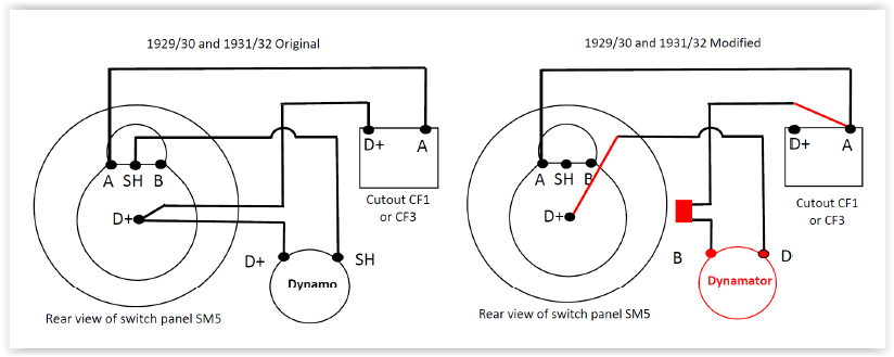
1931/32 cars (cars using DEL dynamo/CF3 cut-out,
and SM5 switch panel)
This is very smilar to the 1929 circuit. The main difference being the
change of cut-out. Therefore:-
1. Fit Dynamator as above. Note positions of wire connections, very important.
2. Connect the wire previously fitted to the ‘D’ terminal on the dynamo (this is
the larger of the terminals) to the ‘B’ terminal on the Dynamator.
3. Connect the wire previously connected to the ‘F’ terminal of the dynamo (this
is the smaller of the terminals) to the ‘D’ terminal on the Dynamator.
4. Identify Cut-Out. Remove the fuse. Remove wire connected to the ’D‘ terminal
and connect to terminal A. (Terminal D remains unconnected.
Do not replace the fuse).
5. Identify the rear of the lighting switch. There are two wires connected to
terminal D. Remove these wires from terminal D and connect together with a small
connecting block.
6. Remove wire connected to terminal ’SH’ and reconnect it to terminal ‘D’.
(terminal ‘SH’ is left empty).
7. Check your wiring carefully and reconnect battery.
8. Job done.
See previous diagrams for 1929/30 car, the
diagram is the same.
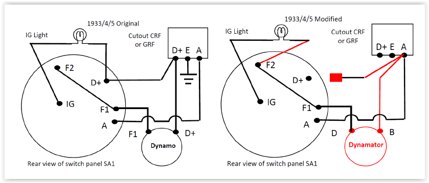
1933/4/5 cars (cars using C35a dynamo/CFR
cut-out and SA1 lighting switch. (These dynamos often have a
small box fitted on top of the dynamo).
1. Fit Dynamator as above. Note positions of wire connections, very important.
2. Connect the wire previously connected to the ’D’ terminal on the dynamo to
the ’B’ terminal on the Dynamator.
3. Connect the wire previously connected to the ‘F’ terminal on the dynamo to
the D terminal on the Dynamator.
4. Identify the cut-out. Remove the wires connected to terminal ‘D’ and connect
them to terminal ‘A’.
5. Remove the earth wire from terminal E. This terminal remains empty.
6. Locate the rear of the lighting switch Type SA1. Identify terminal D. There
should be two (2) wires connected to this terminal. Identify the wire from the
ignition light and reconnect it to F1/F2. Insulate the
end of the other wire and leave it loose. There will be no connection to
terminal D.
7. Check your wiring carefully and reconnect battery.
8. Job done.
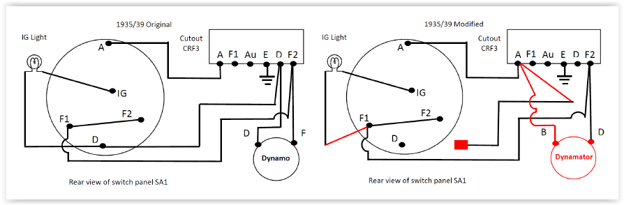
1935 / 39 cars (cars using C35m dynamo/ CFR2
cut-out and SA1 lighting switch).
1. Fit Dynamator as above. Note positions of wire connections, very
important.
2. Connect the wire previously connected to the ’D’ terminal on the dynamo to
the ’B’ terminal on the Dynamator.
3. Connect the wire previously connected to the ‘F’ terminal on the dynamo to
the D terminal on the Dynamator.
4. Identify the cut-out. Remove the wires connected to terminal ‘D’ and connect
them to terminal ‘A’.
5. Remove the field fuse in the cut-out. This is the short fuse adjacent to the
F terminal. Do not replace the fuse.
6. Locate the rear of the lighting switch Type SA1. Identify terminal D. There
should be two (2) wires connected to this terminal. Identify the wire from the
ignition light and reconnect it to F1/F2. Insulate the
end of the other wire and leave it loose. There will be no connection to
terminal D.
7. Check your wiring carefully and reconnect battery.
8. Job done
 FINALLY
The above assumes that cars are wired in accordance with the original circuit
diagrams. After eighty or ninety years this may not be the case and cars may
have any combination of dynamo, cut-out and switchgear of the above.
Also note. The Dynamator will not work if the warning light is faulty (open
circuit) or if the battery is discharged. Make sure all connections are sound
and tight, in particular the connections on the switch panels.
KEEP copy of these instructions handy in case you want
to revert back to using the original dynamo.
Errors and omissions accepted.
Vince Leek
.