DECARBONIZING THE AUSTIN SEVEN
From the Austin Magazine 1934
DECARBONIZING the Austin Seven is a
perfectly straightforward job well within the capabilities of any keen owner.
Before dismantling the engine it is wise to disconnect the battery as a spanner
accidentally dropped on the starter terminal can otherwise cause a dangerous
short circuit. The following procedure should be followed for dismantling: —
(a) Drain the radiator by means of the tap (or, in some
cases, plug) at the base;
(b) disconnect the sparking plug leads; the high tension
terminals are numbered for correct replacement;
(c) disconnect the upper water joint by removing the single
bolt which holds the water outlet to the cylinder head, there is no need to
disturb the hose joint;
(d) disconnect the petrol pipe from the carburetter and also
from the petrol pump or, in the case of early models with a dash tank, from the
petrol tap;
(e) remove the split pin and slip out the carburetter control
rod at the carburetter end and disconnect the strangler wire;
(f) disconnect the exhaust pipe from the manifold by removing
the four bolts;
(g) undo the seven nuts which hold the combined exhaust and
inlet manifold in place and remove the manifold and carburetter complete. On
early models, incidentally, the inlet and exhaust manifolds are separate and the
inlet must be removed first;
(h) remove the 14 cylinder head nuts and lift the head and
gasket.
IF THE HEAD STICKS.
As a general rule, no trouble will be experienced with the head sticking to the
cylinder block, but should any difficulty be encountered the head may be lifted
by means of special tools screwing into the sparking plug holes or,
alternatively, the engine may be turned over by means of the starting handle
when the compression will almost certainly lift the head sufficiently to break
the joint; needless to say, the sparking plugs must be in place for this
operation.
With the head removed the combustion spaces may be
cleaned out in the usual way and the sparking plugs should, of course, be
detached and taken apart for thorough cleaning, subsequently being adjusted so
that the gap is .015 to .018 in.
Attention may then be turned to the cylinder block and the piston crowns should
be scraped clean, rag, of course, being stuffed in the bores above the two
pistons which are at the bottom of their strokes, so as to prevent carbon
chippings finding their way into the cylinders concerned whilst the other two
pistons are being dealt with.
Whether or not the valves are ground in at each
decarbonizing is a matter for the owner to decide. Some people believe in
removing the head and decarbonizing at 2,000-mile intervals, grinding in the
valves at every alternate decarbonizing. Other owners run the engine for
periods of 3,000 - 4,000 miles and attend to the valves on each occasion.
Probably the former is the better course for maintaining absolute efficiency.
TO REMOVE THE VALVES, the cover plate must be taken off and the spring compressor supplied in the tool kit should be used. The compressor, which is in the form of a clamp, should be so placed that its forked end comes underneath the valve collar whilst the screw at its opposite end engages with the centre of the valve head. By turning the screw, the spring will be compressed, so bringing the collar away from the cotter pin in the valve stem and allowing the latter to be removed by means of a pair of pliers.
On models up to and including 1934, split cone cotters
were used to retain the valve springs, these cotters fitting into a tapered
groove in the valve stem. Care must be taken not to lose them on removal as they
are rather diminutive.
When the cotters have been removed the springs can be lowered again by
unscrewing the compressor, the valves withdrawn and the springs and collars
removed. The valves are numbered, and on removal each valve should be placed
with its spring collar and cotter so that each assembly can be replaced in its
original position.
Before each valve is ground in, it is a good plan to
scrape off any carbon deposits which may have collected on the stem or head, a
job which can be done either with a stiff wire brush (a file card is excellent)
or a knife. It is also a good plan at this juncture to clean out the ports so
far as possible, and for this job a bent scraper will be found useful for
reaching round the various corners. A small wire brush may also be a help;
In passing, it is worth advising the owner also to clean out the exhaust
manifold so far as possible as it is not much use having clean ports if the
manifold is thoroughly choked with carbon.
Before grinding-in is commenced, the tappets should be
let down a turn; that is to say, their lock nuts should be slacked off and the
tappet heads screwed down. The reason, of course, is to provide extra clearance
so that there is no risk of the stems touching the tappets and thus preventing
the valve seating properly.
Grinding-in is carried out in the usual manner, a small quantity of grinding
paste being smeared round the valve face, the valve slipped back into position
and then rotated by means of a screwdriver engaged with the slot in its head. A
fair pressure should be exerted whilst the job is being done, and the valves
should be turned in a semi-rotary movement, frequently being lifted off their
seatings and turned to a fresh position. Continuous turning is inadvisable.
There is no need, incidentally, to continue grinding until the whole of the
seating and valve face are polished. Once a thin, continuous polished line
appears on both seating and face, the job may be considered done.
Subsequently the valves should be thoroughly cleaned and
all traces of grinding compound removed from the seatings and ports, whilst the
valve guides should also be cleaned, a job which can very well be done with a
small bottle brush.
Reassembly is a straightforward repetition of dismantling, except that owners
may find a little difficulty in dealing with the split cotters of early models.
The best plan is to smear a little thick grease on to the end of the valve stem
so that the cotters may virtually be stuck in position whilst the spring is
being lowered. Needless to say, the valves will have to be adjusted, a job which
is done simply by screwing the tappet head in or out until the correct
clearance is obtained, and then tightening the lock nut.
Correct tappet adjustment can be obtained only when the engine is hot, the
specified clearance being .004 in. for both inlet and exhaust. As a preliminary
setting, however, a clearance of .006 in. may be given for the inlets and .008
in. for the exhausts.
REASSEMBLY
No snags are likely to arise during subsequent reassembly of the engine after
decarbonizing, but owners are advised to have available a new cylinder head
gasket (price 2s.), a new manifold gasket (price 10d.), a new washer for the
water connection (price ld.), and a new exhaust pipe washer (price 3d.). With
care, of course, the old gaskets can often be used again, but new ones should be
on hand in case they are required. To put back a doubtful gasket is false
economy. The cylinder head gasket, by the way, should be smeared on each side
with grease.
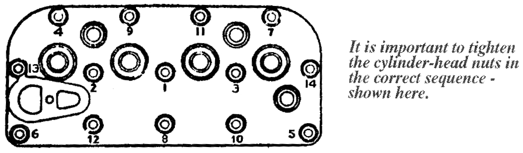
The only other point of importance concerns the cylinder head nuts, which should
be screwed up until they are finger-tight and then given their final tightening,
a turn at a time, in the order shown in one of the accompanying illustrations.
The remainder of the reassembly process calls for no comment, but it is worth mentioning that when an engine has been completely down, Austin mechanics assemble the cylinder block, valves and head as a unit on the bench instead of replacing the block separately. Owners, however, may find it easier to put back the block first and then replace the head.
The fan belt should be adjusted so that there is no visible slack, but the belt is not under tension when the engine is stationary.
A point about which owners are sometimes in doubt is the engine mounting. The crankcase is bolted to the chassis at four points and, on models up to 1934, the bolts should be kept dead tight. On subsequent models rubber washers are employed to insulate the chassis from engine vibration, and in this case the nuts should be sufficiently tight to prevent any free movement, but not so tight that the rubber washers are unduly compressed. The nuts are secured by split pins, which must be replaced if they have been disturbed. As engines increase in age, the rubber washers tend to compress somewhat, and this may be counteracted by tightening as just described. If, however, the washers are perished, there is nothing for it but to replace them.