Capacitors (Condensers) –
How they’re made and why they fail
By John Cornforth (DA7C)
The condenser (nowadays called a capacitor) is a vital part of the traditional points and coil ignition system used in later Austin 7s. When the contact points open, the capacitor allows the several amps of current flowing in the coil to drop to zero in a rapid but controlled manner. This change in current induces a peak of 100 to 200 volts on the coil primary, which is stepped up to 7 to 14 kilovolts at the secondary – enough to cause a spark at the plugs under operating conditions from idle to full power. The capacitor value is a compromise. If it’s too small, more arcing takes place at the points reducing their life. If it’s too large, the current changes too slowly and the peak voltage is reduced. The ideal value is in the range 0.2 to 0.4 microfarads but is not unduly critical. Lucas originally chose 0.4 microfarads for the Austin 7, but later replacements may be 0.2 microfarads. With no capacitor at all, not only does severe arcing take place at the points but more importantly even with new points the primary and secondary voltages are severely reduced. My tests showed no more than 7 kilovolts even with the coil output open circuit. The result is that the engine may start with difficulty and idle, but when the plugs demand greater firing voltage as the throttle is opened and cylinder pressure increases, a bad misfire will ensue. Continued operation allows the points to burn up and go high resistance, causing a further reduction in output voltage and a worsening misfire.
1920s to 1950s A capacitor of this period consists of two aluminium foil plates typically 0.2 thou thick. These are separated by a dielectric of wax impregnated paper 0.6 thou thick. The dielectric prevents the plates from shorting and also increases the capacitance by 3 times compared to air. It is made just thick enough to withstand the required peak working voltage of several hundred volts without breaking down. The total area of each plate is about a square foot, but for a more convenient shape it is made about an inch wide and 18
Capacitor schematic showing possible faults
Lucas 400308 Capacitor in a Ruby DK4A Distributor
feet long. Two layers of foil and two layers of dielectric are made into a sandwich and then rolled up like a Swiss roll. By staggering the layers slightly, the two plates stand proud one at either each end, where they are squashed over to give a contact face with a short low-resistance path.
The capacitor roll is housed in a closed end metal can, which has an earth tab and a “hot” terminal for connection to the points. A paper sleeve prevents short circuits to the inside of the can. The roll face at the earth end connects via a star shaped spring washer to the can, and the face at the hot end connects via a pimpled metal disc joined to the output terminal. This terminal is held in place by insulating sealant. When finished, the spring washer is compressed and the pressure it exerts ensures good electrical contact at both roll faces.
Many of these decades-old originals are still in service, despite being tasked with high voltage and high current pulses, heat cycling and vibration. If you have one of these, leave it fitted !
However, waxed capacitors are prone to failure when the dielectric no longer
insulates properly, e.g. due to a pinhole or ageing aggravated by high temperatures or
over-voltage. Once a tiny arc has taken place between the plates, the dielectric
may carbonise. Unsurprisingly this will weaken the spark or stop it altogether.
properly, e.g. due to a pinhole or ageing aggravated by high temperatures or
over-voltage. Once a tiny arc has taken place between the plates, the dielectric
may carbonise. Unsurprisingly this will weaken the spark or stop it altogether.
If measured with a handheld test ohm meter, a failed capacitor may show a steady leakage resistance of less than a megohm, or even a complete short circuit. Unfortunately, some capacitors measure OK with the low voltage of a test meter, but fail at higher voltage. Testing at high voltage was once done by garages using mains powered instruments, but these have now gone the way of brake drum lathes and Tapley meters ! The only way testing can readily be done at home is by substitution in a working engine.
1960s
to 1980s In the 1960’s Polyester film began to
replace waxed paper. It is much more resistant to insulation failure so leakage
and short circuits are now rare. However, another type of failure may occur
when either of the end contacts fail or go high resistance, e.g. due to
corrosion caused by dissimilar metals in conjunction with residual moisture.
This corrosion may go on steadily for years hidden from sight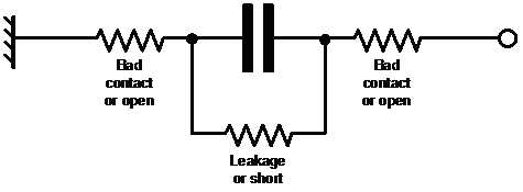 whether the capacitor is in use or not. Bearing in mind that the pulse current
through the capacitor is several amps, even a small resistance will cause
problems. This type of fault may show up as an intermittent misfire, possibly
only when hot or under vibration. The bad contact may arc over in operation,
further degrading the contact resistance. Alternatively, the arcing may
temporarily micro-weld the end contact and the capacitor will work OK whilst the
car is in use, but when laid up it will corrode again and go bad. Frustratingly,
even tests with a sophisticated handheld test meter having a capacitance range
will often still show a normal value.
whether the capacitor is in use or not. Bearing in mind that the pulse current
through the capacitor is several amps, even a small resistance will cause
problems. This type of fault may show up as an intermittent misfire, possibly
only when hot or under vibration. The bad contact may arc over in operation,
further degrading the contact resistance. Alternatively, the arcing may
temporarily micro-weld the end contact and the capacitor will work OK whilst the
car is in use, but when laid up it will corrode again and go bad. Frustratingly,
even tests with a sophisticated handheld test meter having a capacitance range
will often still show a normal value.
The dismantled capacitor shown above caused a severe misfire when hot, but would work again whenever it cooled down.
1990s to present Modern
ignition capacitors are only made for the classic and vintage car replacement
market, and it is hard to know
where and when they were made, even for branded types. Unfortunately, there are
reports that a few do not have ANY form of spring washer inside. It’s unclear
if this is deliberate penny pinching or just designer ignorance. Even if
somehow a good contact pressure was achieved during manufacture by a squeezing
action on the capacitor roll, a few heating cycles and some vibration could
allow the relatively soft material to relax and the end contact pressure to drop
to a feeble amount. The result is high resistance, even without corrosion. This
inbuilt flaw may explain reports of premature failure, or even new part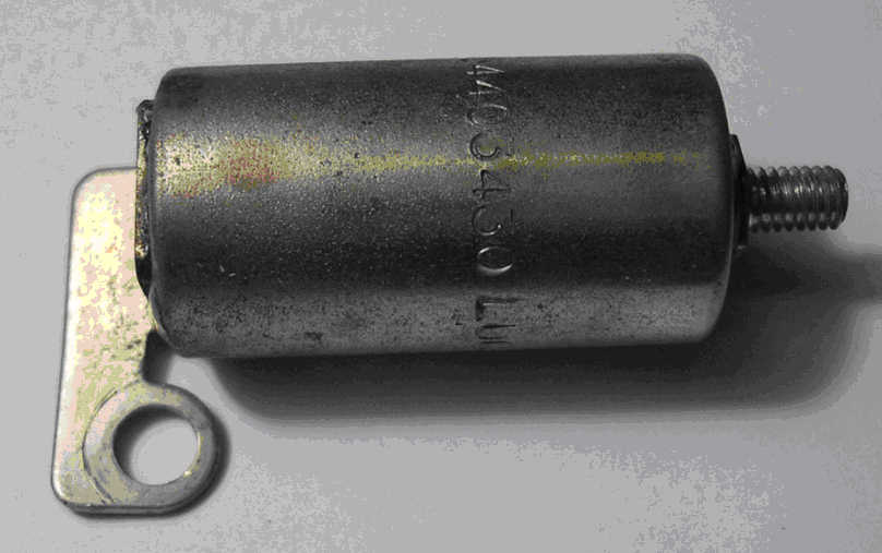 s which
don’t work. Traditionally, capacitors were changed routinely during servicing
as a precaution. There never was much justification for this, and now it would
seem to be a bad idea if the replacement can’t be trusted.
s which
don’t work. Traditionally, capacitors were changed routinely during servicing
as a precaution. There never was much justification for this, and now it would
seem to be a bad idea if the replacement can’t be trusted.
Diagnosis and Cure It is a good idea to carry a tested spare capacitor in the car for emergencies. However, it’s time consuming to fit one into the distributor at the roadside. (Incidentally, the capacitor is only housed there for convenience, mounting elsewhere will still work electrically) An alternative “get you home” measure is to equip a capacitor with two flying leads each
Lucas replacement capacitor – 1980s vintage
about a foot long, fitted with crocodile clips. Don’t make the leads much longer or use too thin a wire. By temporarily shunting this device between the distributor “hot” terminal ( or coil CB terminal ) and earth, an engine can be made to run even if it has a capacitor suffering open circuit failure still in circuit. It does not matter that there are now two capacitors in parallel, if the existing part intermittently “comes good” the total capacitance will simply double. Although this drops the output voltage by about 20%, in my experience the ignition will work with no problems. If adding the flying lead capacitor cures a misfire, the method allows rapid and certain diagnosis of a failed original.
John Cornforth 2013