By Mike Sharp (PWA7C)
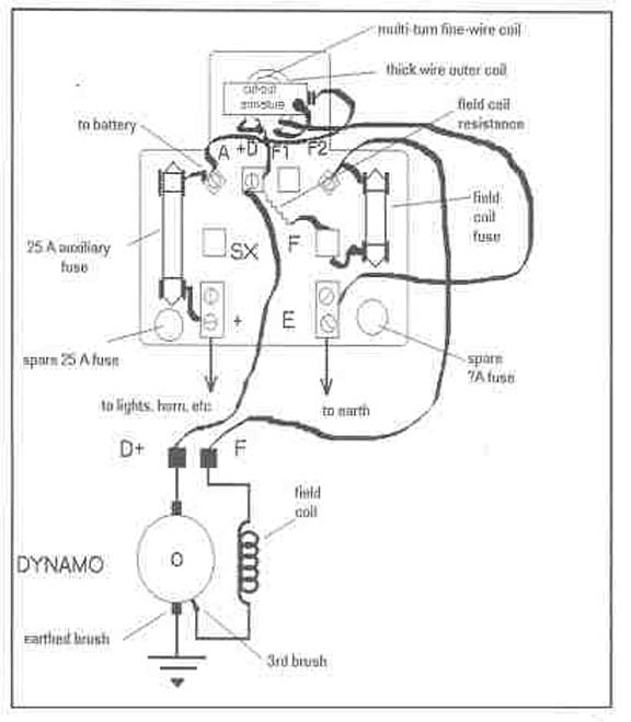
The fusebox fitted to my Box Saloon is of the later
type fitted with two fuses. This is normally found on Rubies but is basically
similar to the earlier singlefuse type. The main difference is an extra fuse
fitted in the dynamo circuit, as can be seen in the accompanying schematic. It
also holds two spare fuses.
The main control on the voltage the dynamo generates (once the cut-out has pulled in) is the load presented by the battery and auxiliary items (coil, horn, lights, etc..) If the connection to the battery and auxiliary items is accidentally broken, then the voltage the dynamo produces can rise to such high levels as to break down the insulation in the dynamo. Herbert Austin decided with the Ruby that this eventuality should be eliminated by putting a fuse in the dynamo fuse circuit. If the voltage and current rise too high, the fuse blows and the dynamo ceases to generate. The contemporary literature warns us to only replace the fuse with the appropriate one, "as seen on the paper inside the glass body of the fuse". Nowhere can I find the specification for this fuse, and the 10A one in my unit is obvious nonsense. Does anyone know the correct fuse? I would guess at about 3 amps, but trial and error, starting at a low amperage, could be used to establish a fuse which is sensitive, without blowing too often.
The ability of the Austin 7 dynamo to generate higher voltages is used in 12V conversions. Very convenient! Some conversions use a 12V regulator which both provides a cut-out coil to pull in at about 12.5V, and a regulator coil to match the dynamo current to the demands of the car. Of course one must match this with a 12V battery and 12V bulbs. Appropriate resistors are normally put in series with the coil and indicators so that they only take the current they were designed for. The starter is left as it is, to briskly turn on its 12V diet!
If using a 12V regulator, one should disconnect the third brush, taking the freed field coil connection to the earthed commutator brush. Otherwise, the high frequency vibration the regulator contacts causes lots of inductive arcing. Not good news. If one is merely adding a 6V regulator unit, the need to disconnect the third brush, still applies. Nothing is lost, electrically speaking, by doing this: the regulator coil does a similar job in limiting the current as does the third brush.... Only better!
Why convert to 12V? Well, 12V bulbs are easier to find, but getting more power from the dynamo is the usual reason. The literature is full of horror stories of people who have pushed the 3`d brush hard against the earthed brush in an attempt to get more current from the unit. This causes the dynamo to overheat and melt the commutator soldered connections. Because the A7 dynamo is totally enclosed, with no through air cooling, it overheats at relatively low currents and the heat generated is proportional to the square of the amps. However, if the volts are allowed to climb to 12V one can get extra power from the dynamo while generating less heat. It is essential not to then stick with 6V units all round, in series with dropping resistors; the power lost in the dropping resistors would negate the extra power gained from converting the dynamo system to 12V!
Various enthusiasts have tried to dispense with the electomechanical cut-out, substituting a large-current diode. This can cause problems with the dynamo "not winding itself up" to generate current. My guess involves the residual magnetism in the A7 field coil - unlike a Volkswagen 6V unit, the A7 poles are made of very soft iron which accordingly retain only a low level of permanent magnetism when switched off. And it can also easily lose this magnetism on standing or being knocked about. As explained in my earlier article, a significant reverse current flows from the battery into the dynamo before the cut-out actually cuts out. This reverse current re-enforces the residual magnetism in the field poles. This reverse current does not occur if a diode replaces the cut-out.
One useful characteristic of the A7 dynamo is that the polarity of the soft iron field coils can be readily reversed to change from positive to negative earth, or vice versa. For example, to make sure your dynamo is suitably polarised for a negative earth system, disconnect the lead at the F terminal of the dynamo, then briefly connect the F terminal with a separate wire to the battery positive - do not try to achieve a similar effect (as is sometimes recommended) by pushing down the armature of the cut-out so as to close the contacts. The reverse current flowing through the cut-out's current coil may keep the contacts closed and burn out wiring (unless you act promptly).
The famous Volkswagen 6V dynamo has a high level of permanent magnetism. This means it can start to generate at low rpm, but the field coils cannot be opposite-polarised as described above. Instead, the field coil terminals must be reversed to change the battery polarity or to correct for reverse direction of rotation.
To check or adjust the pull-in voltage of your cut-out, remove the unit from the car and connect the D+ terminal of the unit to the positive of a 12V battery. Connect the earth terminal of the unit to the negative of the battery through a variable resistance of about 50 ohms. Then starting the rheostat at a high value, gradually reduce its resistance until the cut-out pulls in. Then increase the resistance again until the cut-out drops out again. With a voltmeter between the D+ and E one can see the corresponding voltages.
The unit on my box saloon cut in at 7.8V and dropped out at 5.3V. This means I have to have a lot of revs before I get charge into my battery. If I drove a lot in the dark, it would make sense to bend down the armature stop, bringing the armature closer to the coil core. I simulated this by putting a piece of card between the armature and its stop. It then pulled in at 6.6V and dropped out 5.3V again. The pull-in voltages are meaningful in this simulation, but the drop-out voltages less so - there is no reverse flow through the "current coil", as would occur in practice. As well as adjusting the pull-in voltage by bending the armature stop, one could connect the earth block E on the unit to earth, via a variable resistor. One can then get the cut-out to pull in at any voltage, by adjusting this potentiometer.... including the 12V needed for a 12V conversion! It could even be made adjustable (or set resistors switched into circuit) from inside the car. It is important to note that no other earth connections are made to the unit's E terminal block if a resistor is to be inserted in the circuit for control purposes.
MIKE SHARP
From the PWA7C Magazine with many thanks