
The advantage of the S.U. electric fuel pump over the mechanical type of fuel pump is mainly that it is self priming and only real disadvantage being that the pump is dependent on a supply of electric power.
The petrol pump consists
of three main sub-assemblies: (1) the valve body; (2) the coil housing assembly;
and (3) the contact assembly (Fig.1).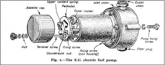
The Valve Body
This consists mainly of a hollow brass or aluminium alloy casting which contains the filters, inlet and outlet unions and their valve assemblies. The inlet valve on the latest type of pump is fitted with a light spring to prevent syphoning action from the fuel tank fuel line whenever the pump is mounted higher than the tank. The valve chambers are connected to the diaphragm pumping chamber by drillings in the casting.
The diaphragm, which is clamped between the valve body and the coil housing assembly, consists of the diaphragm membranes themselves, the armature and the brass contact-breaker actuating rod. The diaphragm membranes are riveted in the armature, which is in turn permanently fixed to the brass rod.
The Coil Housing Assembly.
This is basically a cast-iron cylinder fitted internally with a coil of copper wire wound on a soft iron core with a central hole through which the brass rod from the diaphragm assembly passes in order to operate the contact breaker assembly (Fig. 2). On the diaphragm end of the coil housing there is a ledge between which and the diaphragm armature fits eleven spherical-edged rollers which permit perfectly free oscillation of the diaphragm assembly and which act incidentally as a stiffener for the diaphragm.
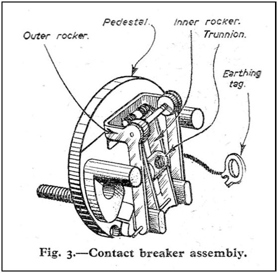
The Contact Breaker Assembly
The contact breaker
assembly is considered by many to be a fascinating and complicated little piece
of mechanism; fascin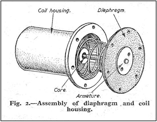 ating
it is, perhaps, and highly ingenious but not so complex. It consists mainly of
two rockers, an inner connected by a small trunnion block to the diaphragm brass
rod, and an outer, to which the lower contact breaker points are fitted; the two
are hinged at the same end and with the same pivot and connected at the other
end by small "toggle over" springs (Fig. 3). The contact breaker points are
tungsten tipped, which ensures long life if the pump is properly adjusted and
not permitted to be abused, such as by permitting the existence of obstructions
on the suction side of the pump, etc.
ating
it is, perhaps, and highly ingenious but not so complex. It consists mainly of
two rockers, an inner connected by a small trunnion block to the diaphragm brass
rod, and an outer, to which the lower contact breaker points are fitted; the two
are hinged at the same end and with the same pivot and connected at the other
end by small "toggle over" springs (Fig. 3). The contact breaker points are
tungsten tipped, which ensures long life if the pump is properly adjusted and
not permitted to be abused, such as by permitting the existence of obstructions
on the suction side of the pump, etc.
Cycle of Operations
The cycle of operations
in the S.U. pump is quite simple and occurs as follows: when the pump is
inoperative, the outer rocker is in the "up" position and the contact breaker
points closed, but as soon as the ignition is switched on, current passes to the
pump terminal, from there through the coil and back to the contact on the spring
blade (which is screwed to the Bakelite pedestal), from there to the contacts on
the outer rocker and finally to earth (or return circuit in the case of double
pole wiring systems). This action energises the coil for the duration of contact
and the coil, as it is an electro-magnet, attracts the iron armature and
diaphragm towards it, thus inducing fuel to flow into the diaphragm chamber via
the inlet valve. When the armature reaches very nearly to the end of its travel,
the "toggle over" mechanism on the contact breaker operates which flicks the
outer rocker back, instantly breaking the circuit, thus causing the magnetic
field in the coil to collapse and the diaphragm spring to force the diaphragm
back to its original position, an action which forces fuel from the diaphragm
chamber through the outlet valve to the carburetter. As soon as the diaphragm
reaches the end of its delivery stroke, the outer rocker flicks up to make
contact again and, once more, the coil is energised and the cycle is repeated.
The rate of this cycle taking place is, of course, governed by the fuel
requirements at the cylinders because, as the fuel is consumed, the carburetter
float chamber level falls, thus opening the needle valve which allows the
pressure in the fuel line between the pump and carburetter to fall and as it
does so the diaphragm forces fuel into the fuel line in an endeavour to maintain
pressure. Whenever the float chamber is full the pump ceases to operate and the
diaphragm remains in the suction
 position
(with contact breaker points open).
position
(with contact breaker points open).
Trouble Tracing
In the event of the fuel pump giving trouble, the things which are most likely to go wrong are the contact breaker points, which after prolonged use get blackened and perhaps burnt owing to sparking. The best method of cleaning the points is to place a piece of stiff card between them, squeeze them together with the fingers and withdraw the card. If the points are burnt and require dressing, it will be necessary to remove the contact breaker rocker assembly from the pump in order to do the job properly. Great care must be exercised when dressing these points on a grindstone for not only must the points be ground properly, but not too much material removed, otherwise the tungsten tip will be removed, leaving the base metal behind which will give a very short life indeed. It is better if the points are badly burnt, to replace the contact assembly completely. The latest S.U. fuel pumps incorporate a condenser in the Bakelite end cap which, it is claimed, prevents sparking and consequently contact breaker points erosion, which increases the pump service life even more. A 1 mfd. condenser fitted between the pump end terminal and earth should prevent sparking across the contact breaker points on older models if this modification is required to be incorporated.
The Diaphragm
The diaphragm on pumps other than of the latest type may swell and cause laboured operation if run on certain types of premium fuel. This is overcome on the latest type of pump by fitting a Neoprene diaphragm which is completely immune from effects of any type of fuel used. Another trouble causing the diaphragm action to be laboured is that of the diaphragm membranes sticking together or of a vapour lock between the membranes. This is overcome in latest type pumps by reducing the number of diaphragm membranes to two and perforating one of them.
The Valves
The valves, of course,
will not function if they are held open by particles of grit or other foreign
matter; the way to discover whether this is happening or not is simpl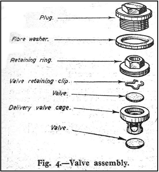 y
to observe whether the pump strokes and delivers fuel or not. If the former is
the case (and assuming, of course, that there is fuel in the tank) then the
valves are stuck open and they will have to be cleaned out. This can be done
in situ on the vehicle by disconnecting the fuel lines and pumping
compressed air through the inlet valve; the air will pass right through the pump
and come out of the outlet union, cleaning the outlet valve as well. It is
suggested that a tyre inflator be employed as the producer of the compressed air
in order to ensure that no damage is done to the pump, which might occur if a
full blast from the 100 lb.+ per square inch service station supply was
employed.
y
to observe whether the pump strokes and delivers fuel or not. If the former is
the case (and assuming, of course, that there is fuel in the tank) then the
valves are stuck open and they will have to be cleaned out. This can be done
in situ on the vehicle by disconnecting the fuel lines and pumping
compressed air through the inlet valve; the air will pass right through the pump
and come out of the outlet union, cleaning the outlet valve as well. It is
suggested that a tyre inflator be employed as the producer of the compressed air
in order to ensure that no damage is done to the pump, which might occur if a
full blast from the 100 lb.+ per square inch service station supply was
employed.
Blockage
Should the pump labour whether the fuel tank line is connected or not, then there is blockage in the suction side of the pump and the first stage is to clean the fuel filters in the pump. If the pump then strokes freely while still disconnected and labours on re-coupling the fuel tank line, then there is obstruction in that fuel line which can best be cleaned by cleaning the fuel tank and fuel line filters (if fitted) and by blowing compressed air down the fuel line from the pump end. The best way to tell whether a pump is labouring or merely stroking slowly (as at idling engine speed) is to feel it - if the pump is hot (taking into consideration the normal temperature and not forgetting the influence of engine heat) then the pump is labouring. These pumps will still function even when they are so hot that it is unbearable for the hand to remain touching. Removal of the end cover and observation of the contact points will also show whether the pump is labouring - if it is, the points will be closed for most of the time. It is very bad indeed to allow these plumps to overheat because the coil insulation may break down and if it does, then possibly
the most expensive part of the pump has failed.
Faulty Contacts
A suggested method of
trouble tracing and getting the pump to re-start, if it should fail to operate,
might start at giving it a sharp tap with the hand. If this is effective, road
vibration will, in all probability, keep the pump operating, but this trouble is
a fair indication that the contacts need attention and possibly the diaphragm
toggle adjustment is inaccurate owing either to contact points’ erosion or a
swollen diaphragm caused by the use of certain types of fuel.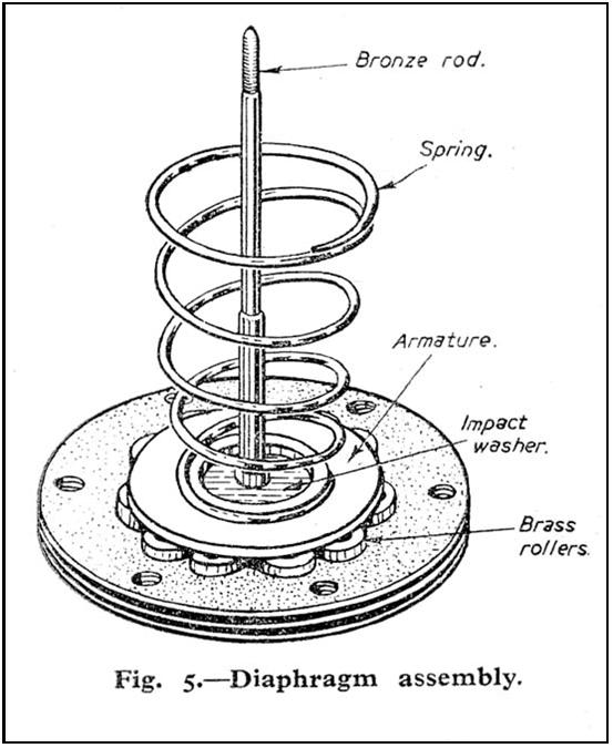
Should the pump still fail to operate, check whether current is reaching the pump terminal by testing with a test lamp to earth; "flashing” is not to be recommended as there is a possibility that the fuse will blow or the ammeter be damaged. If this is not effective then it is likely that a poor connection in the pump itself exists. If this is so it may be that the terminal nut inside the Bakelite cover is not tight. Finally, clean the contact breaker points as previously described. This sequence of operations should exonerate or trace faults in the electrical side of the pump; the next stage is to check the “hydraulic" side of the system.
"Hydraulic" Side
First disconnect the fuel line to the carburetter at the pump and switch on - if the pump functions then blockage exists in that line probably in the form of a stuck carburetter float chamber needle valve or foreign matter which has eluded the pump filters and built up an obstruction. These can easily be remedied by freeing the needle valve and blowing compressed air from a tyre inflator down the pipe from the carburetter end.
If, after this, the pump still does not function property then check for obstruction in the suction side of the pump as previously described. Assuming that even this has not succeeded and pump operation is slow and laboured, the likely trouble is that the diaphragm membranes are stuck together. These can be freed only by unscrewing the coil housing from the valve body casting and unsticking the diaphragm carefully from these two components (so as not to lose any rollers) then separating the membranes and replacing, being careful not to rotate the diaphragm in the coil housing as this is done, otherwise the "toggle" adjustment will be affected.
Before tightening the coil assembly down on to the valve body casting the diaphragm must be stretched either by holding the contact breaker points closed (by wedging a match under the fibre rollers on the outer rocker or similar method) and applying current to the terminal or by wedging beneath the trunnion block in the inner rocker, either action will hold the diaphragm stretched up.
If the fuel pump persistently misbehaves despite adjustment and shows signs of wear, then a thorough reconditioning is the only solution.
Reconditioning the Fuel Pump
As previously mentioned the pump can be divided into three main sub-assemblies: (1) The valve body; (2) The coil housing assembly; and (3) The contacts assembly.
The Valve Body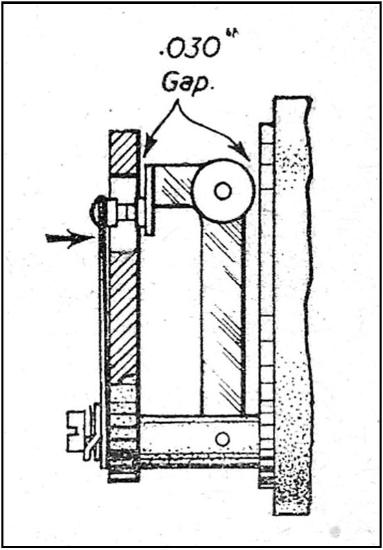
The valves should be removed from the housing and inspected for wear, especially on their seats - they should be replaced even if only slight wear is apparent, not because it is necessary, for these valves have an extremely long life, but to ensure trouble-free operation and peace of mind. (See Fig. 4.)
The fibre washers on the assembly should also be renewed and the casing itself examined for cracks or other damage which might have occurred by previous mishandling - these, of course, will have to be repaired or replaced.
Before replacing the valves ensure that all components are scrupulously clean, especially the filter and interior of the valve body casting, and remembering to replace the disc valves smooth side downwards; make certain that the valve retaining clip is correctly located in its groove in the delivery valve cage and if fibre washers are fitted that the thin washer goes under the cage and the thick one on top: a thick fibre washer is also fitted beneath the filter plug and inlet union. Certain pumps have a spring fitted between the valve cage and foot valve - this is to prevent syphoning on pumps located above the fuel level in the tank.
The Coil Housing
This also includes the diaphragm and armature assembly (Fig. 5). First, it must be clearly understood that no attempts whatever must be made to remove the coil from the casing - this is carefully located on assembly with special press tools and its position is considered critical; in fact, nothing must be done to the coil or its housing except perhaps to renew the insulation on the wires leading out of the top end ensuring, of course, that they really are insulated.
The diaphragm must be inspected for signs of chafing, punctures, continuing right through all the membranes (remembering that on the latest type two-membrane diaphragms, one membrane is intentionally perforated to ensure freedom from vapour locks between the membranes) and undue wear on the armature and contact breaker operating rod.
The eleven brass rollers which locate the armature correctly should show no signs of "flats" being worn on their spherical edges and the wear on the axial faces should not be excessive (this is usually evident in the form of a step sometimes as much as 0.003in deep). This step is not of importance unless it causes "sticky" operation of the diaphragm. It is imperative however, that "flats" do not exist on the rollers. The armature part of the diaphragm should not show traces of wear nor should the brass rod unless perhaps by mishandling. The diaphragm spring should be replaced if it appears fatigued when comparing it to a new one - it should not be stretched to increase its loading on the diaphragm. The diaphragm impact washer must be in place and, finally, remember that it is the large diameter of the diaphragm spring which fits into the coil housing and the small diameter which rests on the armature. The adjustment afforded to the contact breaker assembly by the diaphragm is mentioned later.
The Contact Breaker Assembly
This assembly, possibly,
is where wear and maladjustment become most obvious and although, if properly
adjusted, little trouble should be found with the contact assembly large
mileages, it is here where most wear is evident.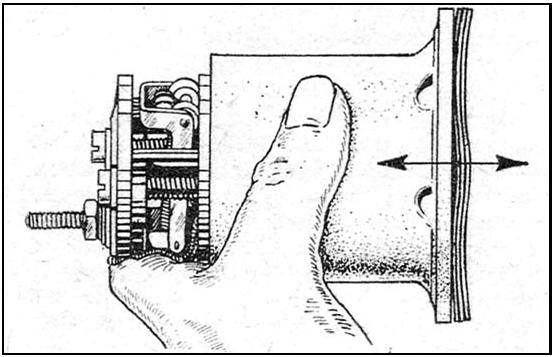
One must watch for burnt, eroded contact breaker points, a worn or ridged hinge pin, cracked Bakelite pedestal, faulty wiring (poorly insulated) and damaged toggle springs. If the contact breaker points are burnt they may be carefully re-faced, but if they have worn excessively the whole double rocker and upper contact spring blade must be replaced.
The hinge pin should be replaced if it is ridged - a genuine replacement must be obtained as it is case-hardened and it can therefore be seen that if a piece of wire is used instead, that it will wear rapidly. If the pedestal is cracked then it must also be replaced.
Reassembly
When reassembling the contact breaker, once again ensure that everything is clean. The rockers should fit freely at the hinge pin otherwise the contact breaker becomes sluggish, but no side play is permissible either as it permits the contact points to get out of line. If adjustments and "squaring up" of the rocker
is necessary it can be done either by bending with the fingers or a pair of thin-nose pliers - needless to say, great care must be exercised.
The upper contact spring
blade should next be fitted to the pedestal beneath the tag and should make
contact with the rocker contact when the outer rocker is in the halfway position
- it should not be so stiff that it prevents full travel of the rocker either.
This adjustment is checked simply by pressing the spring blade down on to the
pedestal and measuring the gap between the top of the rocker and the pedestal
and between the white fibre rollers and top of the coil housing which in both
cases should be 0.030in. If the clearance is incorrect the tip of the spring
blade must be bent so that it is (Fig. 6).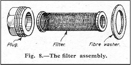
When reassembling parts on to the terminal remember that it is the following order which must be followed: (1) the spring washer; (2) the tag; (3) the lead washer; (4) the 2BA nut; (5) the Bakelite cap; (6) another 2BA nut; (7) the wire and finally (8) the terminal nut. It is necessary that this order is followed, otherwise a poor contact may result or even a cracked pedestal if anything is left out, owing to tightening the 2BA nut which holds the Bakelite cover in place.
All connections must be soldered and tags fitted wherever wires lead to nuts or screws for fixings (remembering that the earthing tag from rocker to pedestal holding-down screw fits above the spring washer in order to ensure good contact).
Toggle Adjustment
Finally, we arrive at the contact breaker toggle adjustment; if this is not done properly the pump will either not function at all or function poorly and probably burn out the contacts rapidly, perhaps the coil as well.
First, the upper contact spring blade is swung out of contact and the diaphragm put in place and screwed into the trunnion block in the inner rocker, then the eleven brass rollers are fitted and the whole screwed in until gentle but firm pressure on the diaphragm does not produce "toggling-over" of the contact breaker rockers (Fig. 7). The diaphragm then is unscrewed one sixth of a turn (one hole on the diaphragm) at a time until gentle but firm pressure on the bottom of the diaphragm produces the toggle-over required - if there is doubt about it, unscrew one "hole" further to be on the safe side, then unscrew a further two-thirds of a turn (four holes). This will be the correct position. Fit the upper contact spring blade back into position and then the assembly to the valve body casting. When this is done before tightening down it is absolutely imperative that the diaphragm be stretched as previously described.
Finally, the pump should be tested which it is not possible to do properly without a test rig which all S.U. agents have, but if a six-volt pump operates satisfactorily on four volts and a 12-volt pump on eight volts, it is a fair indication that the job is satisfactory.